Turbidimeter improvements

a technology of turbidity measurement and turbidity, applied in the field of turbidimeters, can solve the problems of erroneous turbidity readings, large quantities of very costly reagents used in each initial and subsequent primary calibration, and large quantities of very costly reagents, so as to reduce the consumption of costly reagents

Active Publication Date: 2008-09-30
CHEMTRAC
View PDF3 Cites 13 Cited by
  • Summary
  • Abstract
  • Description
  • Claims
  • Application Information

AI Technical Summary

Benefits of technology

[0015]Prior to use, the first element of the sensor block can be swung open like a door. Once the first element has been rotated away from the second element so that their respective flat faces, which are otherwise contiguous when these elements are fully closed, are separated by a sufficiently large angle—an angle which in the preferred embodiment can be up to 180 degrees, the user can easily remove the flow-through sample cell and prepare it for a primary calibration procedure. In order to minimize the consumption of costly reagent used in such a procedure, plugs have been provided for stoppering the elbows mounted on the upper and lower caps. Instead of siphoning reagent away with a standpipe, for example, one can flush any residual liquid from the sample cell by partially filling only the sample cell itself. Likewise, only the sample cell needs to be filled in order to calibrate it.
[0016]Alternately, a closed sample cell, optically matched with the flow-through sample cell, can be used to perform a secondary calibration (calibration verification). The closed sample cell includes an upper opaque cap from which a cap plate and support shoulder extend outwardly. Like the support shoulder in the flow-through sample cell, the support shoulder in the closed sample cell is slip-fitted into the channel defined by the first and second elements of the sensor block when they are fully closed. Without stopping the sample flow stream, one simply swings open the first element, removes the flow-through sample cell, inserts the closed sample cell which has been prefilled with a suitable reagent, closes the first element, and takes the turbidity reading. Care must be taken to index and read both the closed and flow-through sample cells at their respective orientations which produce the lowest background blank value for each sample cell. But in general, this dry method of secondary calibration not only allows one to reuse the reagent employed as the standard but also to perform this procedure quickly.

Problems solved by technology

Unfortunately, in the case of prior art on-line turbidimeters, substantial quantities of very costly reagent must be used with each initial and subsequent primary calibration.
On the other hand, dead spaces in prior art sample cells which lack a bottom outlet port tend to collect settleable contaminants from the sample flow stream.
These contaminants can then reenter the flow stream as a blob, giving rise to erroneous turbidity readings.

Method used


Image

  • Turbidimeter improvements
  • Turbidimeter improvements
  • Turbidimeter improvements

Examples


Embodiment Construction

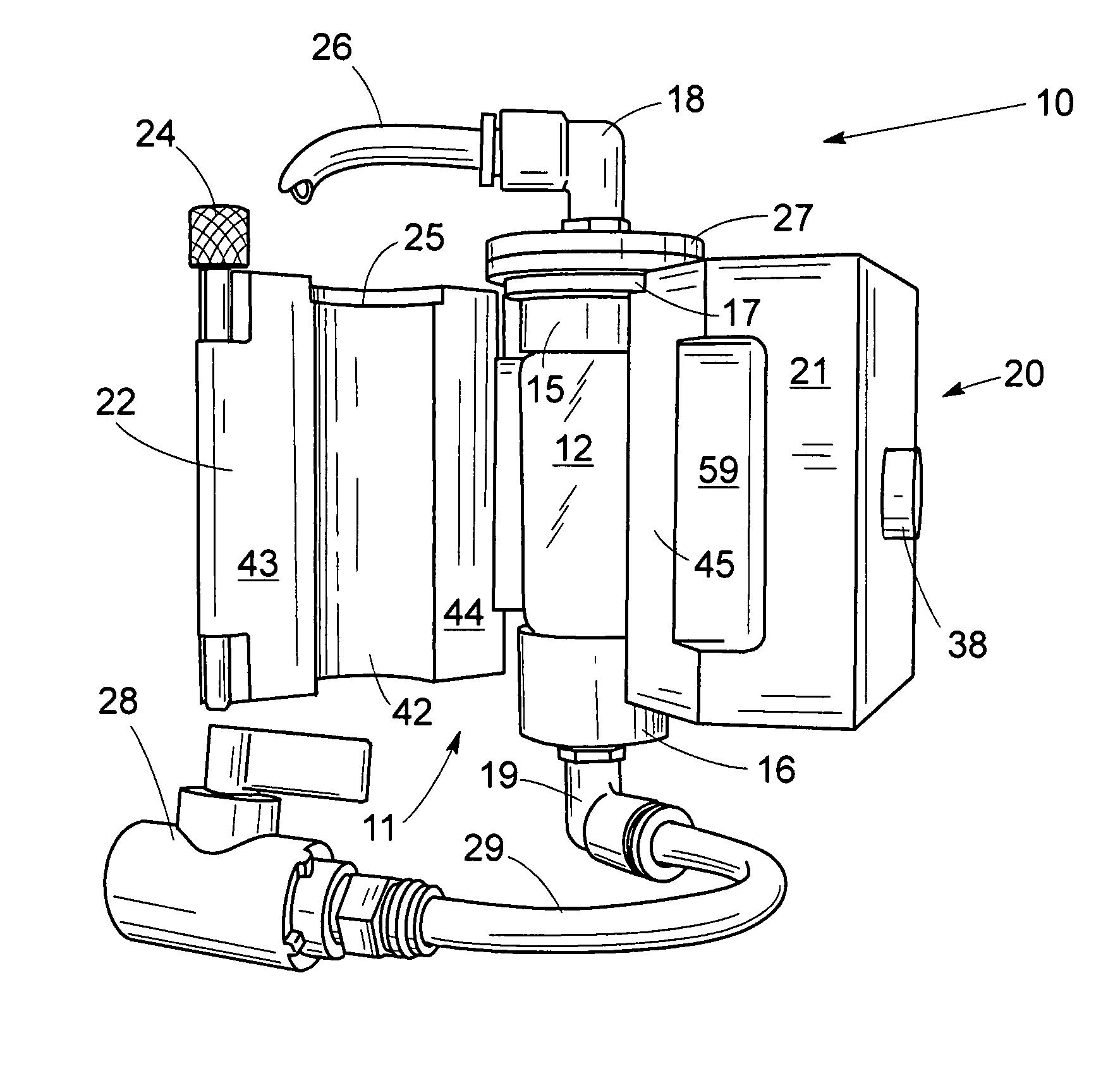
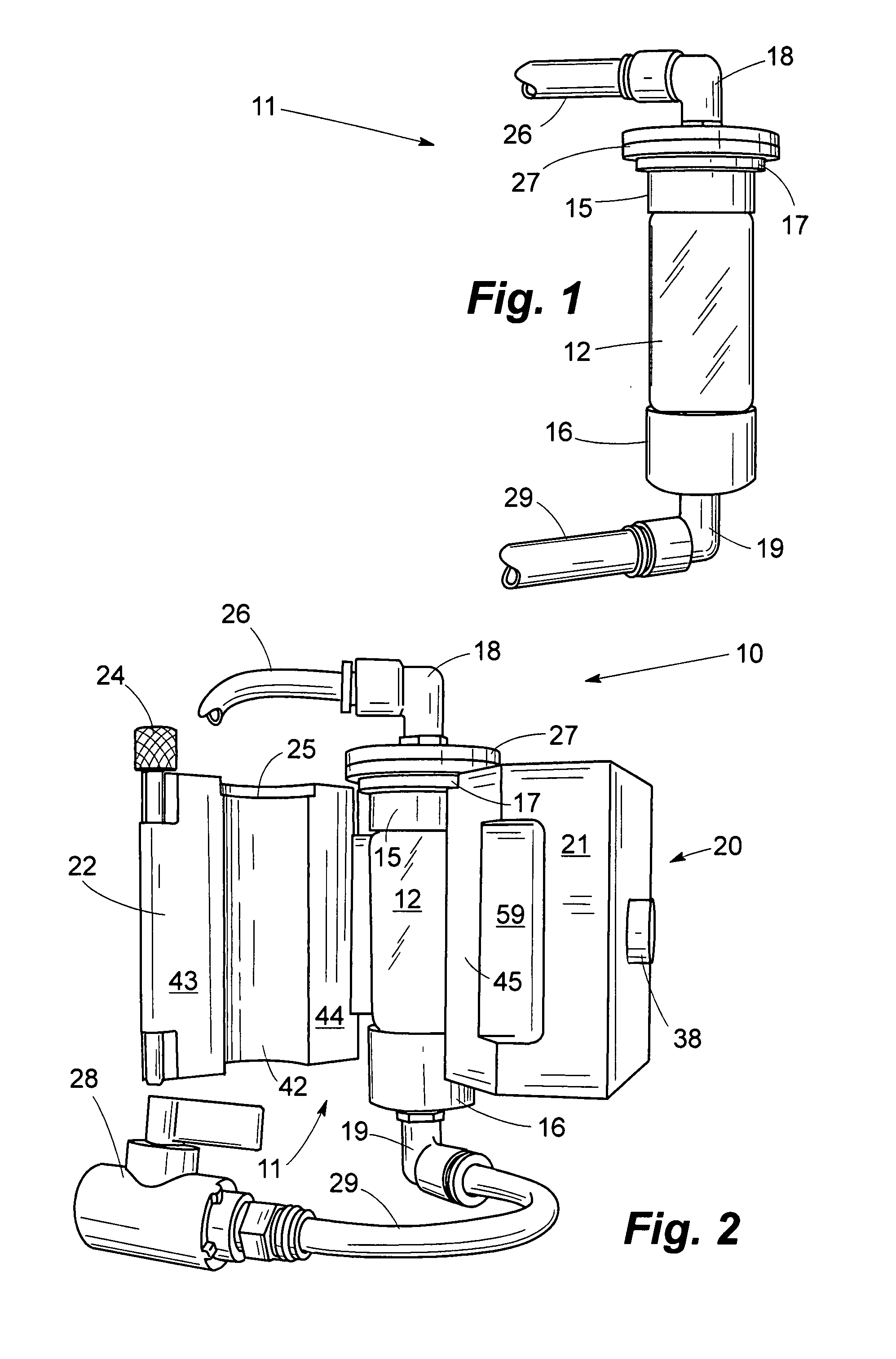
[0024]In the drawings, a novel flow-through sample cell apparatus is indicated generally by the reference numeral 10. The apparatus 10 includes a sensor block 20 having two major components: a movable first element 22 and a stationary second element 21 which are hingedly connected together by a vertically-aligned hinge pin 23. As it is being pivoted about the pin 23, the first element 22 swings open like a door (FIG. 2).

[0025]Also included in the apparatus 10 is a flow-through sample cell 11 having a cuvette with a transparent midsection 12 and end portions 13, 14 which are formed as a single, unitary piece with the midsection. Threadedly engageable with external threads on the end portions 13, 14 are opaque caps 15, 16 which form water-tight seals with them. Protruding from the top edge of the upper cap 15 is a cap plate 27; and beneath it, is disposed a support shoulder 17 over which the cap plate is cantilevered.

[0026]In the preferred embodiment, the lower cap 16 and that portion...


PUM

PropertyMeasurementUnit
angleaaaaaaaaaa
volumeaaaaaaaaaa
turbidityaaaaaaaaaa

Abstract

A turbidimeter with a pair of movable and stationary elements interconnected by a vertically-aligned hinge pin. Interior walls of these elements, when fully closed, define a cylindrical through passageway and an annular shelf which extends outwardly from its upper end. Otherwise, the stationary element, when the movable element has been pivoted away from it, defines one-half of the through passageway bisected lengthwise and a semi-annular shelf. Prior to use, a transparent cuvette can be slideably inserted sideways into the bisected through passageway and suspended there by protrusions on a cap threadedly engaged with the cuvette. The protrusions include a cap plate and an annular support shoulder which, in use, rests on the shelf. With its cuvette insertable sideways, an upflow sample cell, complete with supply and drain fittings fluidly connected to the cuvette, can be readily moved into and out of the turbidimeter to facilitate calibration procedures.

Description

FIELD OF THE INVENTION[0001]This invention relates to turbidimeters and more particularly, to a flow-through sample cell and a holder for supporting the sample cell while its contents are subjected to nephelometric analysis.BACKGROUND OF THE INVENTION[0002]Nephelometric analysis is a well-known method of quantitative analysis in which the concentration of suspended matter in a liquid is determined by optical means. The method is based upon a comparison of the intensity of light scattered by a sample under defined conditions with the intensity of light scattered by a standard reference suspension. The higher the intensity of the scattered light is, the higher the turbidity.[0003]Utilizing a nephelometer with a light source for illuminating the sample and at least one photoelectric detector with a readout device to indicate the intensity of the light scattered at right angles to the path of the incident light, a turbidimeter is usually designed to meet the specifications set forth in ...

Claims


Application Information

Patent Timeline
Patent Type & Authority Patents(United States)
IPC IPC(8): G01N21/01G01N1/10
CPCG01N21/05G01N21/51G01N2021/513
Inventor EVANS, JAMES M.
Owner CHEMTRAC
Why Eureka
Try Eureka