Combined RGB and IR imaging sensor

a technology of imaging sensor and rgb, which is applied in the direction of television system, solid-state device signal generator, picture signal generator, etc., can solve the problems of affecting the color reproduction of images, increasing the cost of lenses, and affecting the use of automotive or consumer digital cameras or cell phone cameras,

Active Publication Date: 2013-05-21
MAGNA ELECTRONICS INC
View PDF526 Cites 75 Cited by
  • Summary
  • Abstract
  • Description
  • Claims
  • Application Information

AI Technical Summary

Problems solved by technology

The IR light from the environment thus may wash-out the color response in the visible spectrum and thus may distort the image color reproduction.
The coating process and added material increase the cost of the lens, sometimes significantly.
The additional cost of two filters and mechanical switches, as well as the reliability of the moving mechanical switch, make such systems undesirable, and such a design is not suitable for automotive or consumer digital cameras or cell phone cameras.

Method used


Image

  • Combined RGB and IR imaging sensor
  • Combined RGB and IR imaging sensor
  • Combined RGB and IR imaging sensor

Examples


Embodiment Construction

Imaging Sensor Description

[0020]The imaging sensor of the present invention comprises a two-dimensional pixelated imaging array having a plurality of photo-sensing pixels arranged or disposed or established on a semiconductor substrate. For example, the imaging sensor may comprise a complementary-metal-oxide-semiconductor (CMOS) or a CCD imaging sensor or device or the like, and may utilize aspects of the imaging sensors described in U.S. Pat. Nos. 5,796,094; 6,097,023; 6,320,176; 6,313,454; 6,559,435; 6,831,261; 6,396,397; 5,877,897; 6,498,620; 5,670,935; 6,806,452; 6,946,978; 7,123,168; 7,004,606; 7,005,974; and / or 5,550,677, and / or PCT Application No. PCT / US07 / 75702, filed Aug. 10, 2007, and / or U.S. patent application Ser. No. 11 / 239,980, filed Sep. 30, 2005; Ser. No. 11 / 105,757, filed Apr. 14, 2005 by Schofield et al. for IMAGING SYSTEM FOR VEHICLE; and / or Ser. No. 10 / 534,632, filed May 11, 2005; and / or PCT Application No. PCT / US2003 / 036177, filed Nov. 14, 2003 by Donnelly Corp....


PUM


Abstract

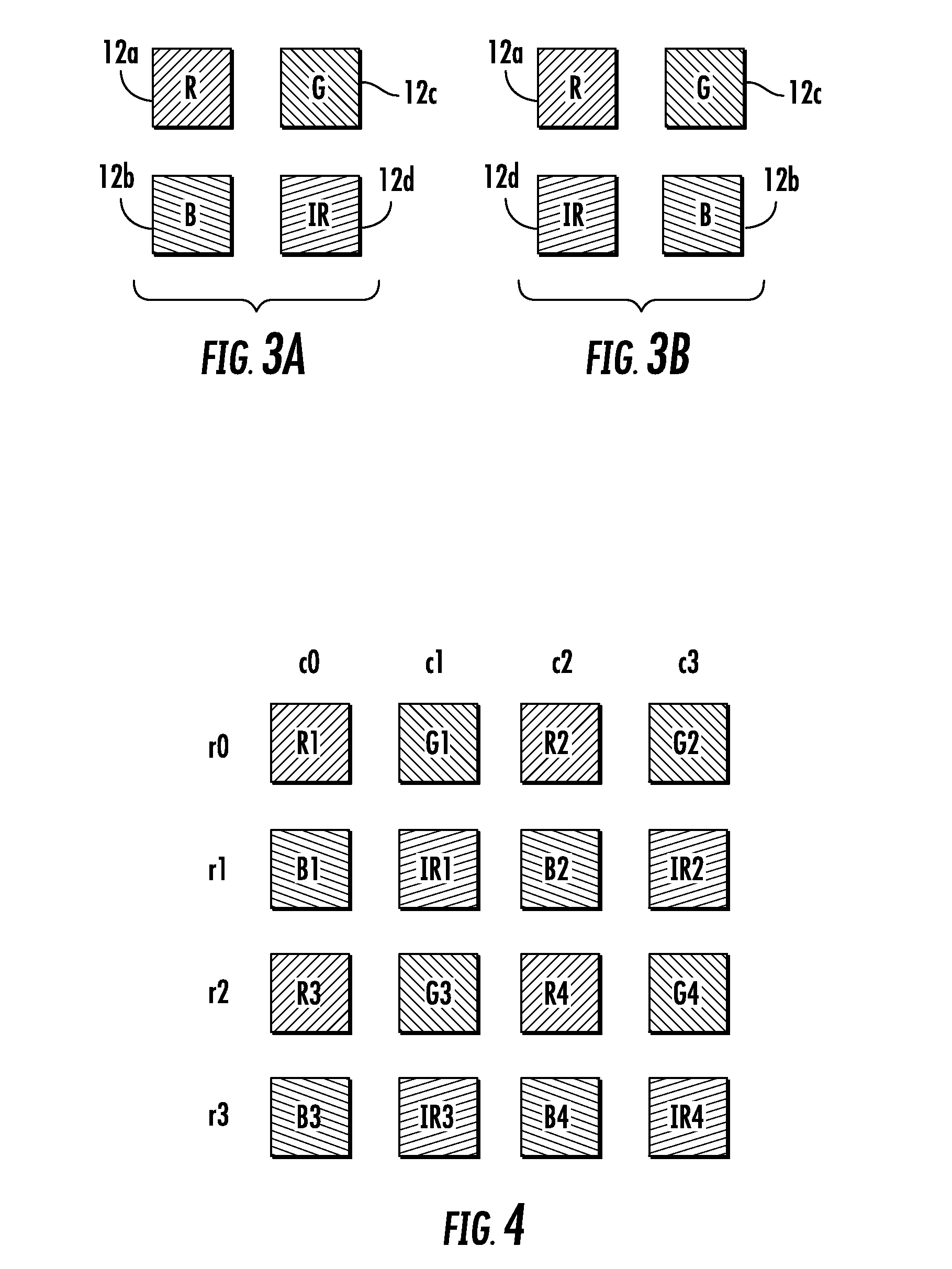
An imaging system suitable for use in a vehicle includes an imaging sensor having a two-dimensional array of photosensing elements, an image processor for processing image data captured by the imaging sensor, and a display for displaying images responsive to the image processor. The array has a plurality of sub-arrays, with each of the sub-arrays having a first pixel sensing primarily a first color, a second pixel sensing primarily a second color, a third pixel sensing primarily a third color and a fourth pixel sensing primarily infrared radiation. The image processor processes the output of the fourth pixel to determine an infrared component of the imaged scene and subtracts the infrared component from the outputs of the first, second and third pixels to obtain a more accurate or true color response for the pixels and to limit or avoid infrared color wash-out.

Description

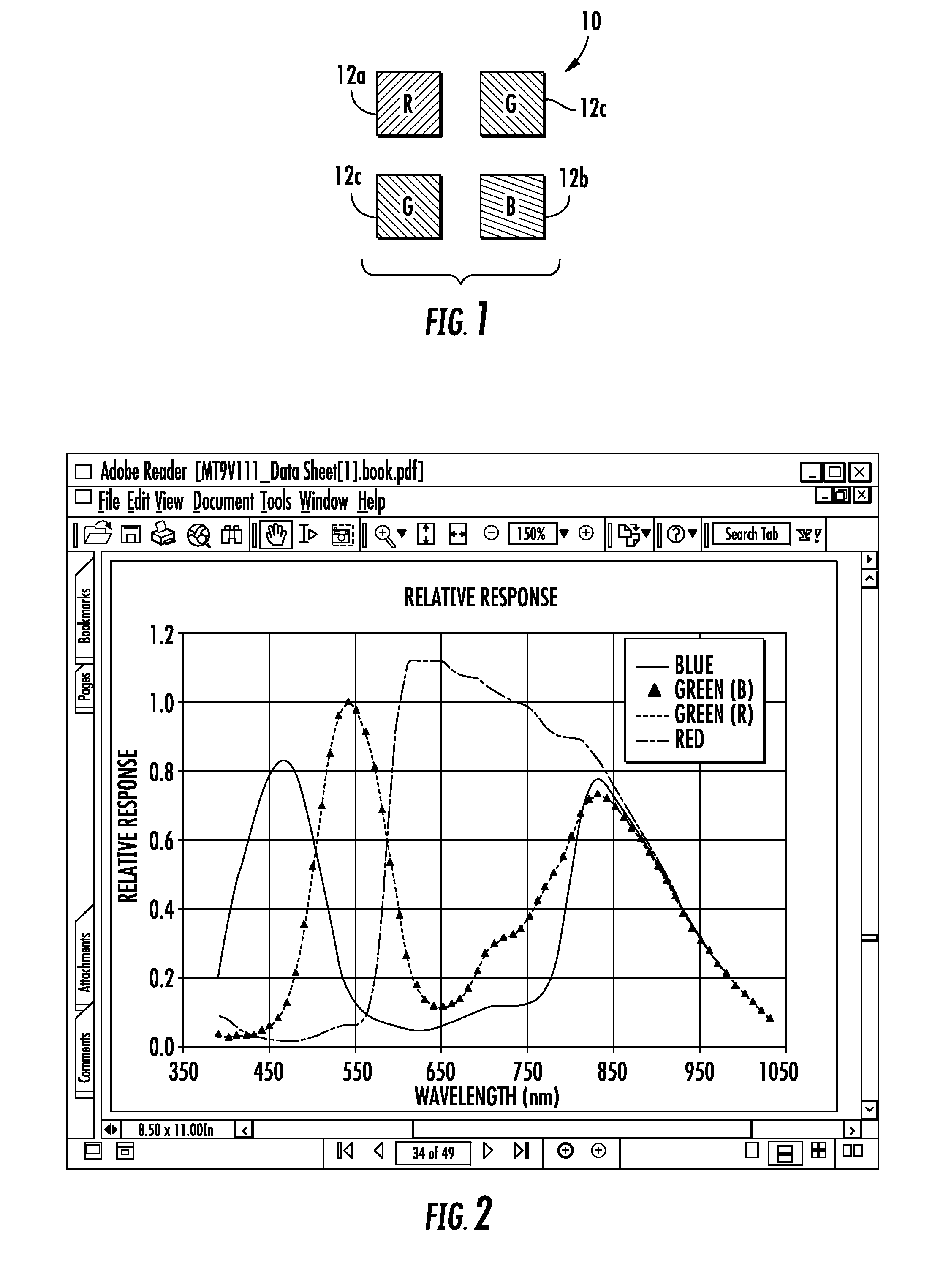
CROSS REFERENCE TO RELATED APPLICATION[0001]The present application claims the benefit of U.S. provisional application Ser. No. 60 / 977,430, filed Oct. 4, 2007, which is hereby incorporated herein by reference in its entirety.FIELD OF THE INVENTION[0002]The present invention relates to vision systems for vehicles and, more particularly, to an imaging sensor or camera for a vision or imaging system of a vehicle.BACKGROUND OF THE INVENTION[0003]Traditional color imagers or image sensors or pixelated imaging arrays use a Bayer pattern of pixels and pixel filters, which has a red-green-green-blue (R-G-G-B) pixel / filter configuration (such as shown in FIG. 1). In such a pixelated array, the sensor includes individual optical filters that transmit red, green or blue colors and that are disposed at or coated on the individual pixels. Thus, there is a “red pixel”12a, a “blue pixel”12b and two “green pixels”12c arranged to form a 2×2 sub-array 10 that is repeated over the pixelated array.[000...

Claims


Application Information

Patent Timeline
Patent Type & Authority Patents(United States)
IPC IPC(8): H04N7/18
CPCH04N5/2258H04N7/18H04N9/045H04N23/45H04N23/843H04N25/131H04N25/135H04N23/11H04N9/646
Inventor LU, YUESHENGHIGGINS-LUTHMAN, MICHAEL J.LIVENGOOD, WILLIAM R.HARRIS, JAMES DANIEL
Owner MAGNA ELECTRONICS INC
Why Eureka
Try Eureka