Vehicle traction mat and associated method

a technology of traction mats and tires, applied in the direction of tread bands/rings, ways, constructions, etc., can solve the problems of ineffective makeshift means, inability to meet the needs of users, and the device of the prior art has not been satisfied, so as to achieve convenient rolling and maximize the grip on the tires

Inactive Publication Date: 2013-05-28
AUBIN GARY A
View PDF9 Cites 20 Cited by
  • Summary
  • Abstract
  • Description
  • Claims
  • Application Information

AI Technical Summary

Benefits of technology

[0012]The body may be selectively rolled and unrolled between cylindrical and planar shapes during non-operating and operating conditions respectively. Such an arrangement provides the unexpected and unpredicted advantage of preventing vehicles from becoming stuck in snow, on ice, in mud, sand or any soft ground where the vehicle's tires may invariably spin without traction. The apparatus may further be easily rolled and stored in its own mesh storage bag thus allowing users to stow away the apparatus in a vehicle's trunk or under the seat when not in use. The apparatus thus eliminates the need to carry space wasting shovels, boards, chains, or sand bags in a vehicle when driving on off-road conditions or on highways in winter.
[0013]The first and second studs may be monolithically formed with the body in such a manner that the second studs remain spaced subjacent to the first studs and the tread layer respectively. A plurality of raised side-walls may extend upwardly from oppositely situated longitudinal edges of the central portion. The side-walls may further be equidistantly offset from a centrally registered longitudinal axis of the central portion and extend parallel to the longitudinal axis along an entire longitudinal length of the central portion. The tread layer may further be raised abo...

Problems solved by technology

Such makeshift means are generally ineffective, being immediately caught and thrown out by the rotating traction wheels, subjecting bystanders to possible injury from the flying objects.
Such devices of the prior art have proven unsatisfactory for numerous reasons, including being overly expensive to manufacture, unsafe to handle because of sharp edges, etc., snow or mud being packed between the protuberances on the ...

Method used


Image

  • Vehicle traction mat and associated method
  • Vehicle traction mat and associated method
  • Vehicle traction mat and associated method

Examples


Embodiment Construction

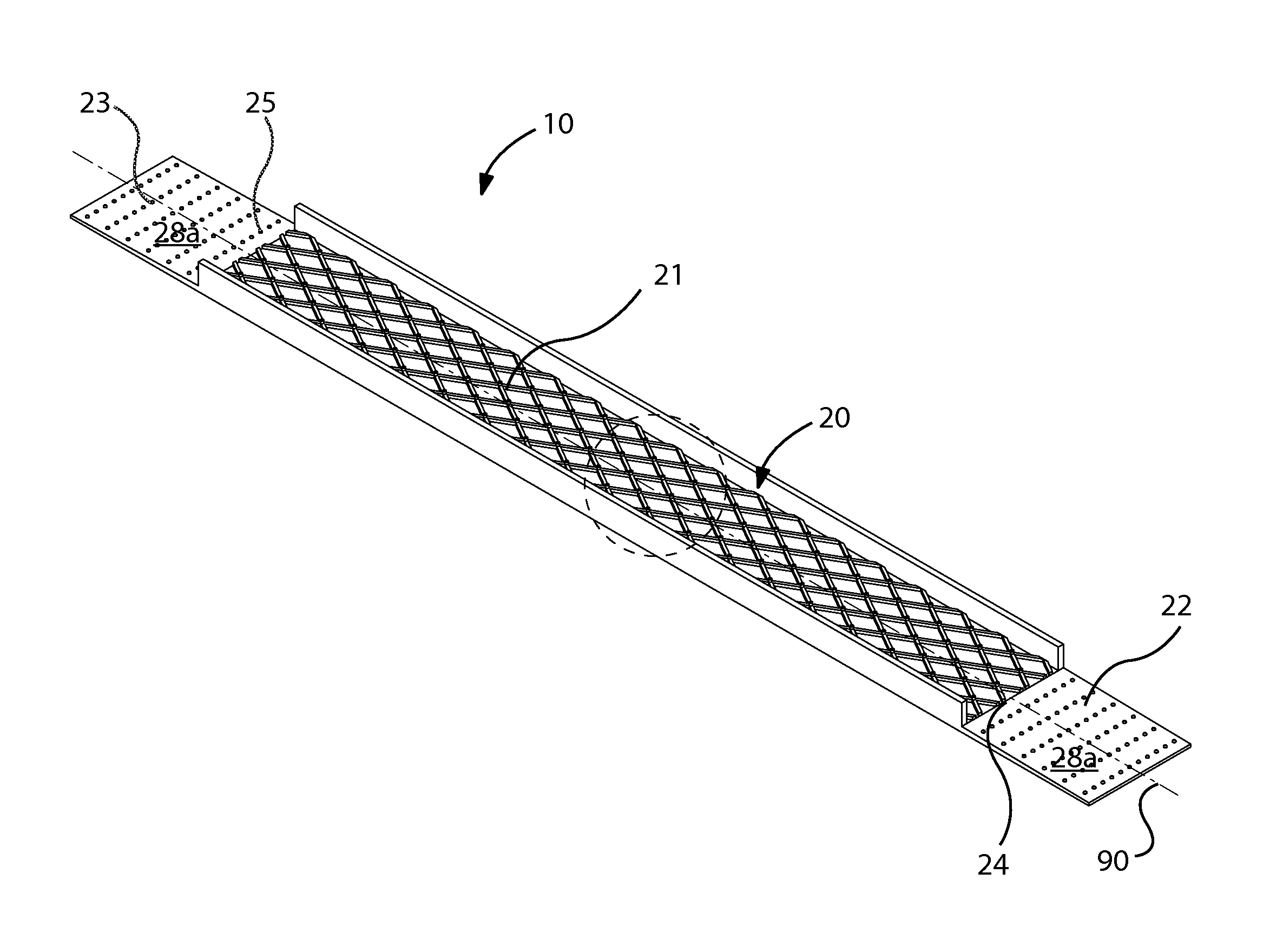
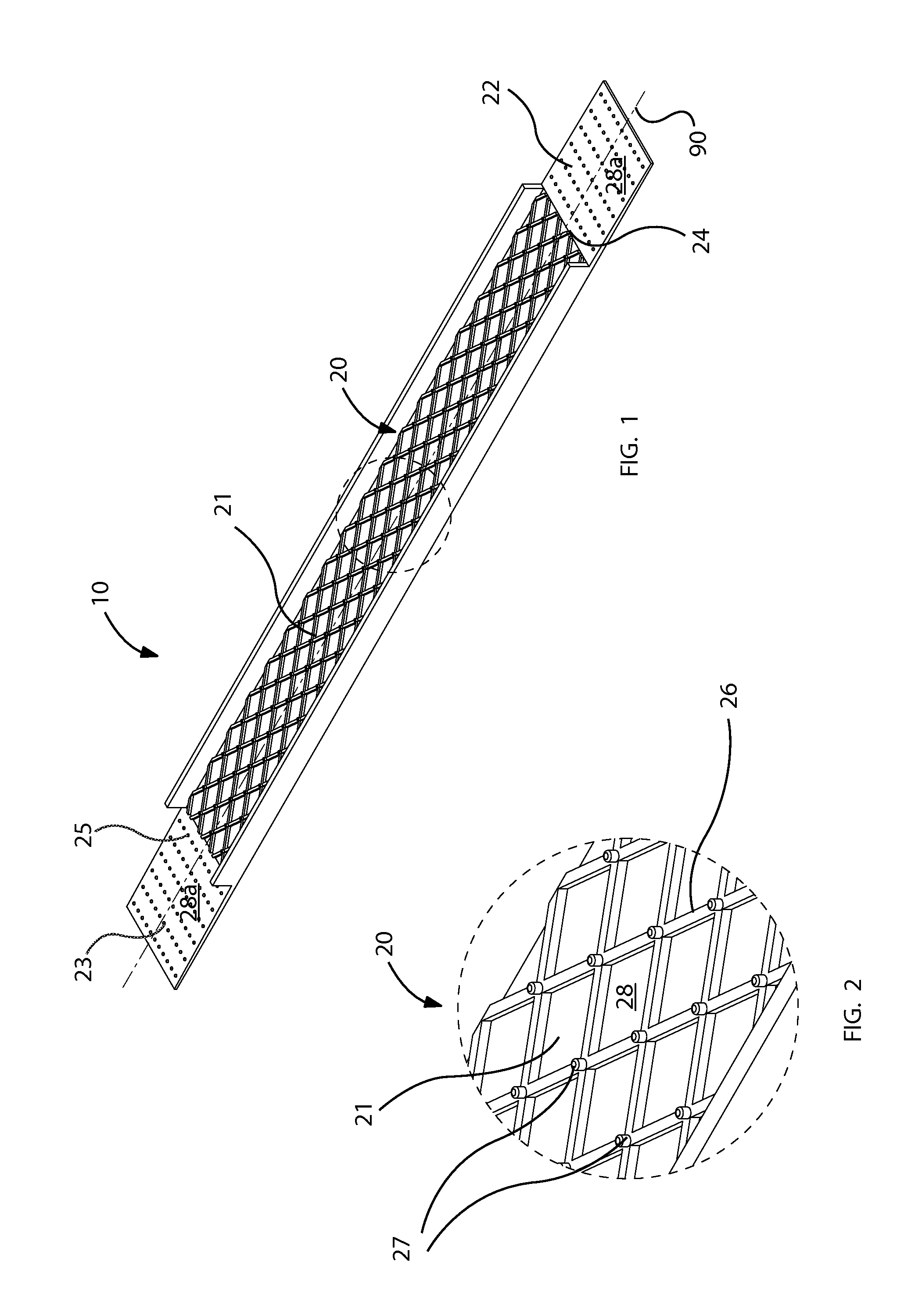
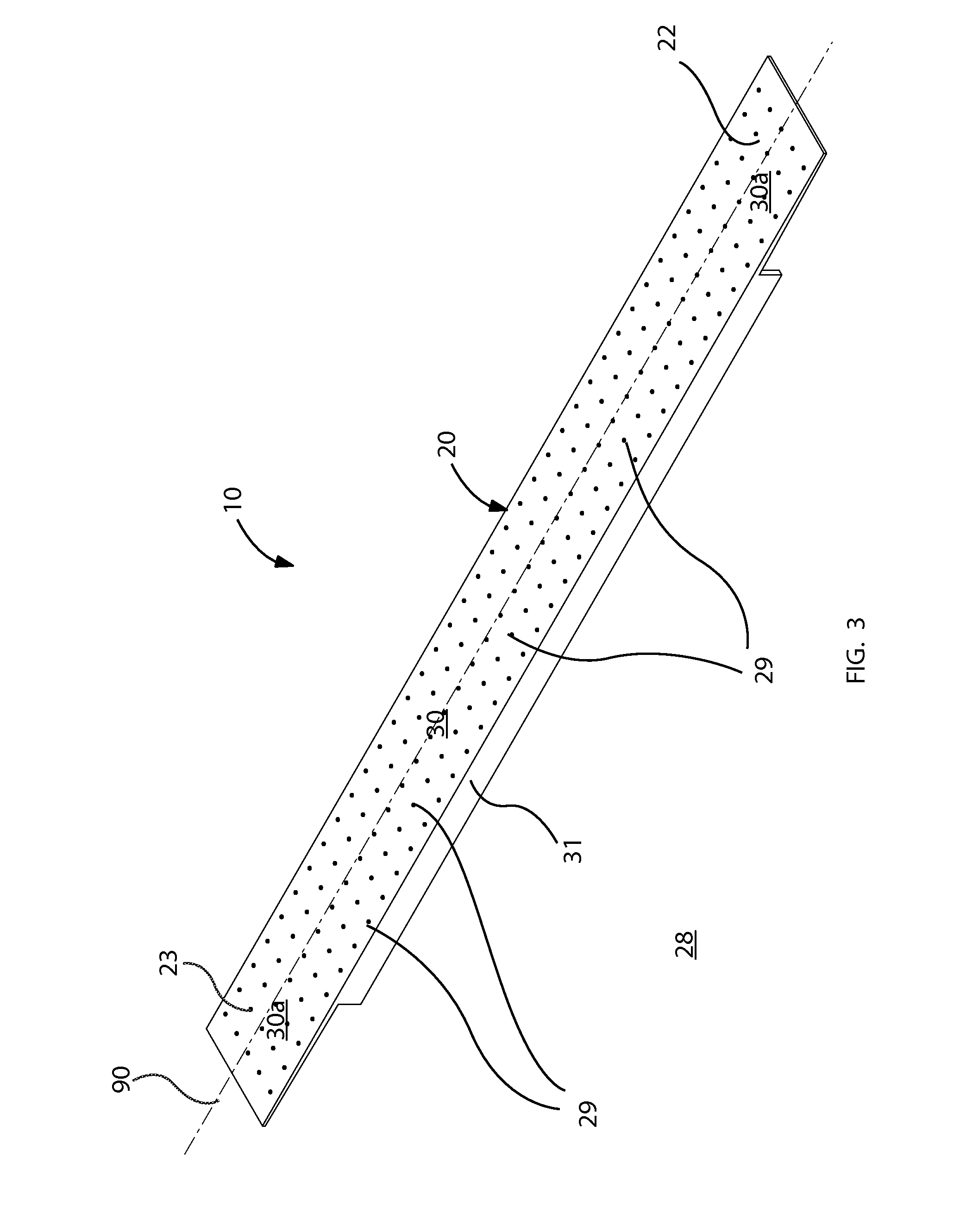
[0029]The present invention will now be described more fully hereinafter with reference to the accompanying drawings, in which a preferred embodiment of the invention is shown. This invention may, however, be embodied in many different forms and should not be construed as limited to the embodiment set forth herein. Rather, this embodiment is provided so that this application will be thorough and complete, and will fully convey the true scope of the invention to those skilled in the art. Like numbers refer to like elements throughout the figures.

[0030]The illustrations of the embodiments described herein are intended to provide a general understanding of the structure of the various embodiments. The illustrations are not intended to serve as a complete description of all of the elements and features of apparatus and systems that utilize the structures or methods described herein. Many other embodiments may be apparent to those of skill in the art upon reviewing the disclosure. Other ...


PUM


Abstract

A vehicle traction mat may include a flexible and unitary body having a central portion. A first and second ramp may be connected to axially opposed first and second ends of the central portion. A tread layer may be positioned on a top surface of the central portion and terminating prior to reaching the first and second ramps. A plurality of first studs may be statically attached to a top surface of the body and protruding upwardly from the central portion such that a top most tip of each of the first studs penetrates out through the tread layer and terminates above the tread layer. A plurality of second studs may be statically attached to the central portion and protruding downwardly therefrom. The body may be selectively rolled and unrolled between cylindrical and planar shapes during non-operating and operating conditions respectively.

Description

CROSS REFERENCE TO RELATED APPLICATIONS[0001]This application claims the benefit of U.S. Provisional Application No. 61 / 233,536, filed Aug. 13, 2009, the entire disclosures of which are incorporated herein by reference.STATEMENT REGARDING FEDERALLY SPONSORED RESEARCH OR DEVELOPMENT[0002]Not Applicable.REFERENCE TO A MICROFICHE APPENDIX[0003]Not Applicable.BACKGROUND OF THE INVENTION[0004]1. Technical Field[0005]This invention relates to vehicle traction mats and, more particularly, to a vehicle traction mat and associated method for providing vehicle operators with an easy and convenient mechanism of providing additional traction to the tires of a vehicle stuck in snow, mud and the like.[0006]2. Prior Art[0007]Traction mats have been used by automobile vehicles for many years to enable the vehicle to be driven out of a rut or pothole by gaining additional traction from materials placed into the path of the drive wheel. Numerous such means have been used by persons stuck in ice or sn...

Claims


Application Information

Patent Timeline
IPC IPC(8): E01B23/00
CPCB60C27/00B60B15/24
Inventor AUBIN, GARY A.
Owner AUBIN GARY A
Why Eureka
Try Eureka