Optical connector

a technology of optical connectors and connectors, applied in the direction of optical elements, coupling device connections, instruments, etc., can solve the problems of high degree of accuracy, difficult for an operator to perform a connecting operation, and practicably impossible to arrange conductive wires having a large width or diameter, etc., to achieve reliable locking properties, easy and accurate manner, and easy unlocking properties

Inactive Publication Date: 2013-05-28
MOLEX INC
View PDF32 Cites 4 Cited by
  • Summary
  • Abstract
  • Description
  • Claims
  • Application Information

AI Technical Summary

Benefits of technology

[0012]Therefore, it is an object of the present invention to obviate the above-described problems encountered by the conventional optical connector and to provide an optical connector having such a configuration that a concave portion having oblique side portion is formed in either one of a front end portion of a plug connected to an optical waveguide and a rear end portion of an abutting portion of a connector housing, the connector housing being provided to be engaged with the front end portion of the plug, and that a convex portion having a circular arc-shaped end portion is formed in the other one of the front end portion and the rear end portion, so that the front end portion of the plug and the rear end portion of the connector housing make multi-point contact with each other, so that the optical connector has high durability and good operability in operation while enabling it to be manufactured at a low cost, in a small size, and with a simple structure. As a result, it is possible to perform positioning of the plug relative to the connector housing in an easy and accurate manner.
[0020]In accordance with the optical connector of the present invention, the concave portion having oblique side portion is formed in either one of the front end portion of the plug connected to the optical waveguide and the rear end portion of the abutting portion of the connector housing, the connector housing being configured to be engaged with the front end portion of the plug, and the convex portion having the circular arc-shaped end portion is formed in the other one of the front end portion and the rear end portion, so that the front end portion and the rear end portion may be in multi-point contact with each other. Owing to this configuration, it is possible to perform positioning of the plug relative to the connector housing in an easy and accurate manner. Moreover, it is possible to realize both easy unlocking properties and reliable locking properties. Accordingly, it is possible to provide an optical connector which has high durability and good operability in operation and can be manufactured at a low cost to have a simple structure.

Problems solved by technology

Although the signal transmission speed may be increased in response to an increase in image resolution, since there is a limit in increasing the inside dimension of the hinge portion, it is practically impossible to arrange a conductive wire having a large width or diameter.
However, according to the conventional optical connector, since the positioning of the plug is carried out by tightly fitting the guide projections 831 to be engaged with the engagement holes of the plug, it may be difficult for an operator to perform a connecting operation.
For this reason, an operation of an operator moving the plug to cause the guide projections 831 to be inserted into the engagement holes requires a high degree of accuracy and is thus difficult to perform.
Moreover, since a direction where the plug is moved relative to the optical connector is limited to only one direction, a degree of freedom in the connecting operation is low.

Method used


Image

  • Optical connector
  • Optical connector
  • Optical connector

Examples


Embodiment Construction

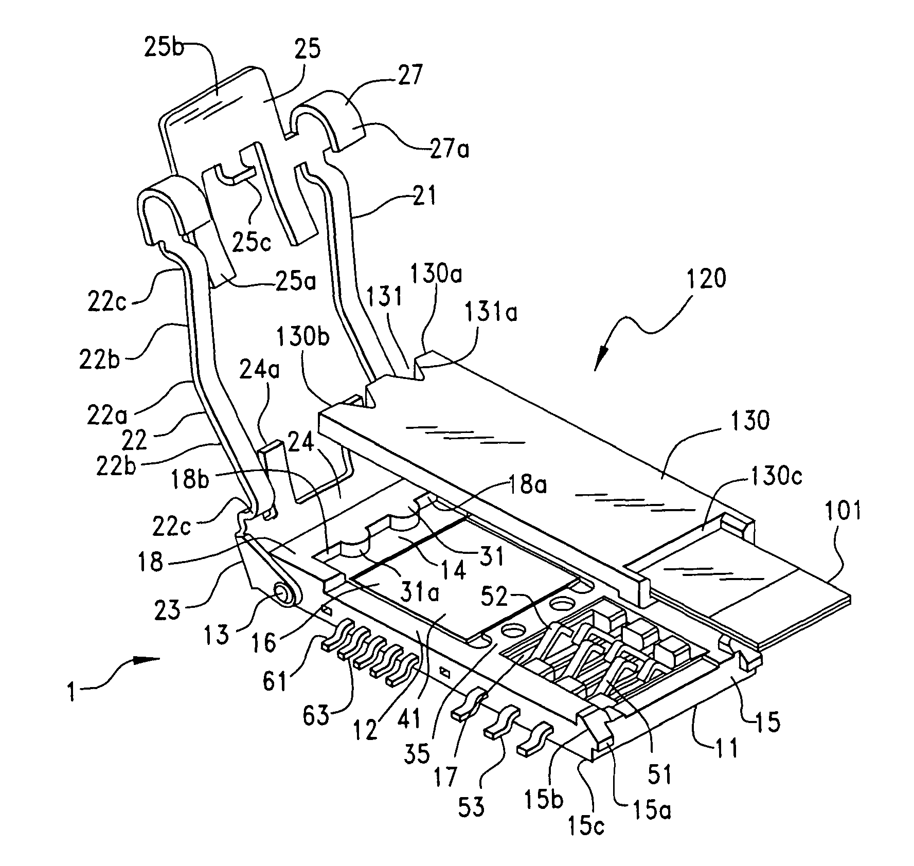
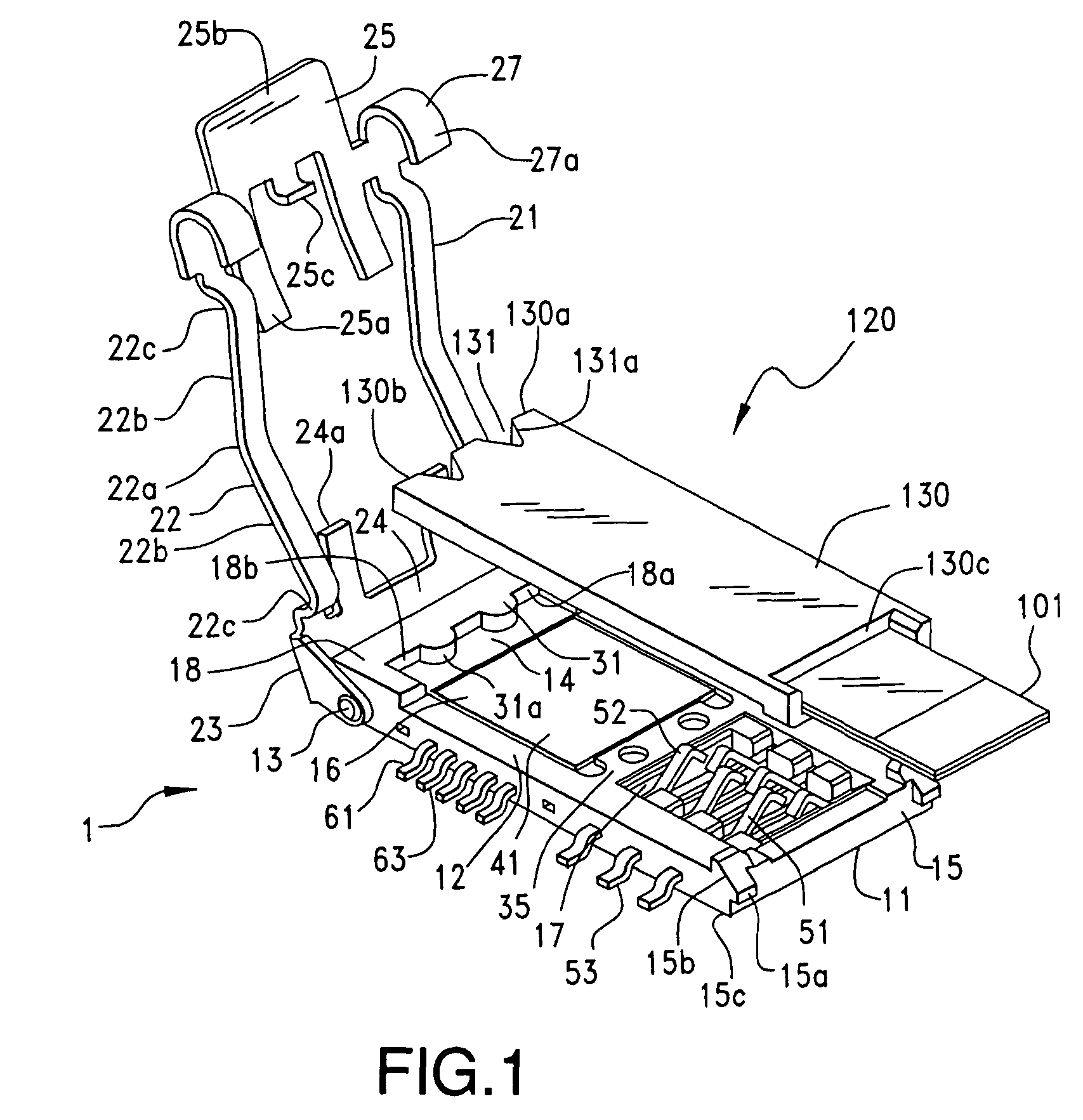
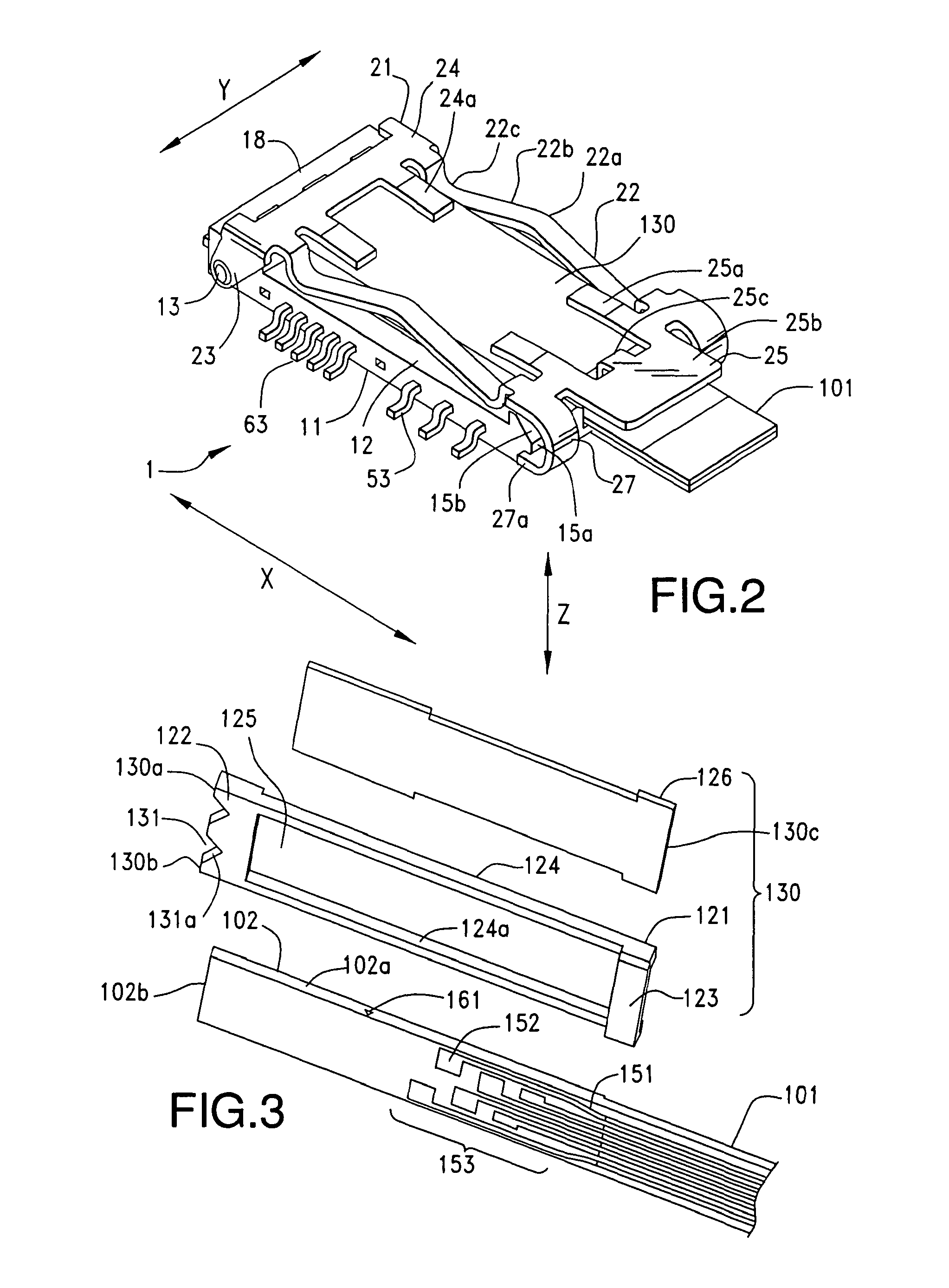
[0031]While the Present Invention may be susceptible to embodiment in different forms, there is shown in the Figures, and will be described herein in detail, specific embodiments, with the understanding that the discussion herein is to be considered an exemplification of the principles of the Present Invention, and is not intended to limit the Present Invention merely to that as illustrated. Further, in the embodiments illustrated in the Figures, representations of directions such as up, down, left, right, front, rear and the like, used for explaining the structure and movement of the various elements of the Present Invention, are not absolute, but relative. These representations are appropriate when the elements are in the position shown in the Figures. If the description of the position of the elements changes, however, it is assumed that these representations are to be changed accordingly.

[0032]Referring to FIGS. 1-2, a receptacle connector as a optical connector according to the...


PUM


Abstract

A connector comprises a housing, a lever and a lock portion. The housing receives terminals. The lever, rotatably attached to the housing, is configured to be rotatable between a first position, where an initial stage of fitting to a counterpart connector is established, and a second position, where the fitting thereof is completed. The lock portion, capable of locking the lever at the second position, is slidably attached to a body portion of the lever, and configured to be slid between a lock position and a lock release position. The lever is provided with a positioning latch-portion configured to latch the lock portion. The positioning latch-portion is provided with a concave latch-portion and a convex latch-portion configured to be elastically displaced to be engaged in or disengaged from the concave latch-portion.

Description

BACKGROUND OF THE INVENTION[0001]1. Field of the Invention[0002]The Present Invention relates, generally, to an optical connector, and, more particularly, to an optical connector having an increased degree of freedom in the connecting operation.[0003]2. Description of the Related Art[0004]In an electronic device or apparatus, such as a personal computer, a cellular phone, a personal digital assistant (PDA), a digital camera, a video camera, a music player, a game machine or a car navigation device, in order to realize both a decrease in the overall size of a casing and an increase in the size of a display screen, the casing is typically configured to be collapsible. In such a case, a flexible printed circuit and conductive wires are arranged so as to pass through an inside of a hinge portion that allows one casing to be pivotably connected with the other casing so that signals can be transmitted through parallel transmission.[0005]Although the signal transmission speed may be increa...

Claims


Application Information

Patent Timeline
Patent Type & Authority Patents(United States)
IPC IPC(8): G02B6/38H01R33/945
CPCG02B6/3883G02B6/3817G02B6/4214G02B6/4228G02B6/4246G02B6/4292G02B6/4416G02B6/38G02B6/42
Inventor SHIMOTSU, AKIHIROARAI, MASAYUKI
Owner MOLEX INC
Why Eureka
Try Eureka