
Wave and water energy converter mounted on bridge supports

Active Publication Date: 2013-06-11
SWAMIDASS PAUL M
View PDF4 Cites 8 Cited by
  • Summary
  • Abstract
  • Description
  • Claims
  • Application Information

AI Technical Summary

Benefits of technology

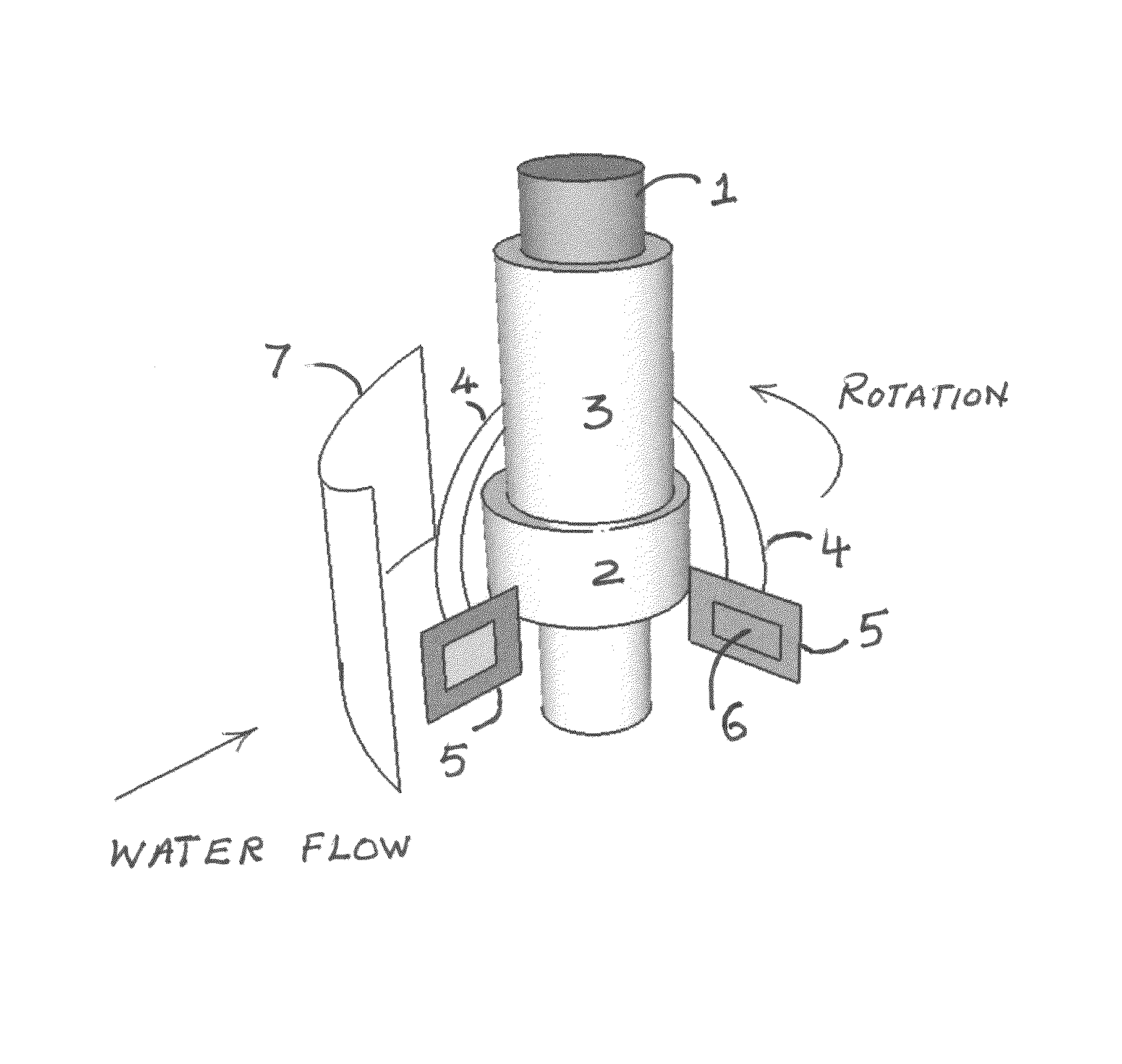
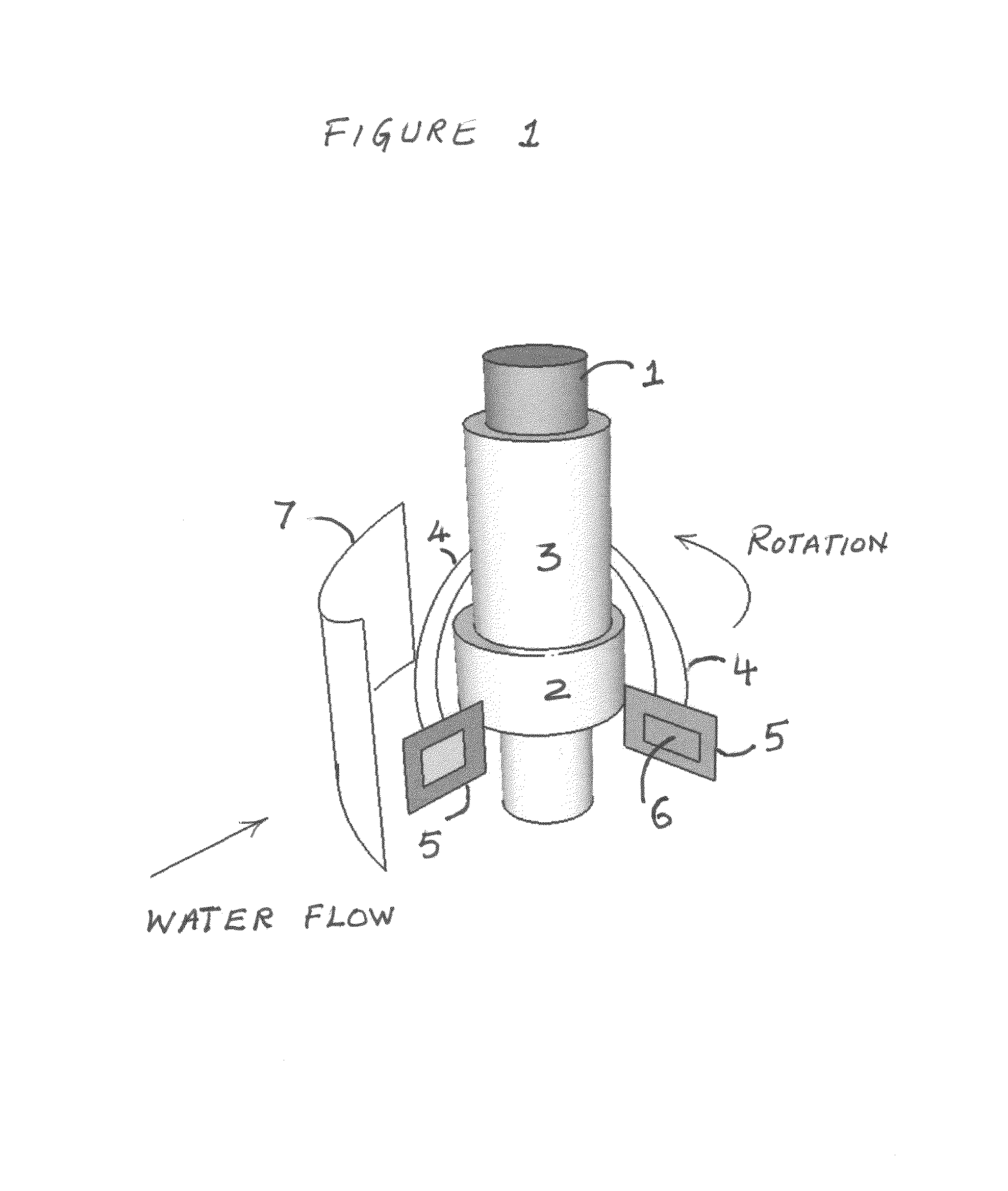
[0005]Bridge columns offer multiple opportunities to harvest wave and related energy from water under the bridge. Bridge-column based WWEC systems include the following embodiments but are not limited to them. The technologies listed below are to be of the appropriate scale to prevent overloading of the bridge columns beyond their

Problems solved by technology

There are no known devices attached to bridge colum

Method used


Image

  • Wave and water energy converter mounted on bridge supports
  • Wave and water energy converter mounted on bridge supports
  • Wave and water energy converter mounted on bridge supports

Examples


Example

Embodiment 2

Pump Lifts Water to an Overhead Tank—Falling Water Turns Turbine

[0022]A large float, which bobs up and down with the waves under a bridge, is attached to one or more rigid arms that are hinged at a high point in the bridge columns. The float or arms are connected to a reciprocating or rotary pump(s) to pump water up to fill water in a large overhead tank located just under the bridge deck. The elevated water in the tank is released through ducts to drive a water turbine(s) below to produce electric power. After driving the turbine, the spent water falls back into the body of water under the bridge.

[0023]Embodiment 2 could be used to pressurize air, gas or any fluid to drive turbines that turn electric generators.

Brief Description of Drawings for Embodiment 2

[0024]FIG. 5: It is a perspective view—bobbing tubular float provides reciprocating motion to a piston in a pump cylinder that lifts water to a tank that hangs just under the highway deck on the top of the bridge colu...

Example

Embodiment 3

Rack and Pinion Drives an Electric Generator

[0032]In this embodiment, the vertical movement of the wave is translated to a linear motion of a geared rack, which drives a pinion attached to an electric generator. The generator shaft has a flywheel to smooth the ensuing rotary motion and power of the generator because the power flowing from the vertical up and down motion of the wave is cyclical, not constant.

Brief Description of Drawings for Embodiment 3

[0033]FIG. 8: shows a cylindrical float 82 surrounding a cylindrical bridge column 81 transfers vertical motion of the wave to a pinion 84 that turns an electric generator.

[0034]FIG. 9: shows a cylindrical float at the ends of arms hinged to bridge columns 91 transfers vertical motion of the wave to a geared rack that turns a pinion 95 attached to an electric generator.

[0035]FIG. 10: shows a cylindrical float at the ends of arms hinged to a bridge columns 101 transfers magnified vertical motion of the wave to a geared rack...


PUM


Abstract

Highway bridge supporting structures that stand in large bodies of water are usefully employed in a novel manner in this invention to inexpensively extract energy from the water under the bridge using new and established apparatus. Alternate energy producing systems from water waves, currents and tides suffer from cost disadvantages incurred in designing and erecting expensive structures that hold them firmly on the ground under the water against fierce wind and water forces. This invention ingeniously uses existing or new bridge structures for mounting water-borne-energy to electricity conversion systems at much reduced cost. The invention will make water energy conversion systems more affordable and will turn existing and new bridge supporting structures into dual-use systems that can not only support bridge decks above but also produce useful renewable energy from the water below; today, bridge structures are not used in this manner.

Description

FIELD OF THE INVENTION[0001]The invention generally relates to the green, renewable alternate energy industry, and particularly to wave and water energy conversion (WWEC) industry by the novel use of bridge supporting structures. The apparatus takes advantage of the strong columns supporting the highway deck overhead. The invention substantially cuts the cost of WWEC systems because these systems may be retrofitted to existing bridge columns as well as to new bridge columns for supporting new highway decks; the cost of the column supporting the energy conversion systems will be associated with the cost of the bridge with this novel invention. Consequently, the cost of the water-energy conversion system becomes substantially lower than what it could have been without using the bridge structure; this invention will turn bridge columns into dual-use structures.BACKGROUND OF THE INVENTION[0002]Water in ocean, sea and rivers offer plenty of energy but the technology to harvest the energy...

Claims


Application Information

Patent Timeline
IPC IPC(8): F03B17/02F03B13/18F03B13/00F03B13/10F03D7/00
CPCF03B13/1815F03B13/24F03B17/065F03B17/066F05B2240/911Y02E10/38Y02E10/28Y02E10/30Y02E10/20
Inventor SWAMIDASS, PAUL M
Owner SWAMIDASS PAUL M
Learn More