
Fiber optic instrument sensing system

a fiber optic instrument and sensing technology, applied in the field of medical instruments, can solve the problems of differential between the actual position, unanticipated or unmodeled constraints imposed by the patient's anatomy, and the control is subject to multiple sources of error, so as to facilitate the estimation and control of the reaction for

Active Publication Date: 2013-06-11
AURIS HEALTH INC
View PDF14 Cites 112 Cited by
  • Summary
  • Abstract
  • Description
  • Claims
  • Application Information

AI Technical Summary

Benefits of technology

[0046]In another variation, a localization system as described herein can use measurement of Rayleigh scatter in the optical fiber. Measurement of Rayleigh scatter can be used to measure strain in the fiber. Such information can be used as an alternate mode of obtaining shape data. Alternatively, Rayleigh scatter can be combined with other localization systems to supplement or improve the localized shape data.
[0048]Methods and devices for calculating birefringence in an optical fiber based on Rayleigh scatter as well as apparatus and methods for measuring strain in an optical fiber using the spectral shift of Rayleigh scatter can be found in PCT Publication No. WO2006099056 filed on Mar. 9, 2006 and U.S. Pat. No. 6,545,760 filed on Mar. 24, 2000 both of which are incorporated by reference herein. Birefringence can be used to measure axial strain and / or temperature in a waveguide. Using Rayleigh scatter to determine birefringence rather than Bragg gratings offers several advantages. First, the cost of using Rayleigh scatter measurement is less than when using Bragg gratings. Rayleigh scatter measurement permits birefringence measurements at every location in the fiber, not just at predetermined locations. Since Bragg gratings require insertion at specific measurement points along a fiber, measurement of Rayleigh scatter allows for many more measurement points. Also, the process of physically “writing” a Bragg grating into an optical fiber can be time consuming as well as compromises the strength and integrity of the fiber. Such drawbacks do not occur when using Rayleigh scatter measurement.
[0054]Shape data can further assist in estimation and control of reaction force between the device and environment. Deflection of measured shape from the predicted free shape belies application of external forces. Estimates of these forces may be used to navigate the environment or if an environment model is available, plan a navigation path.

Problems solved by technology

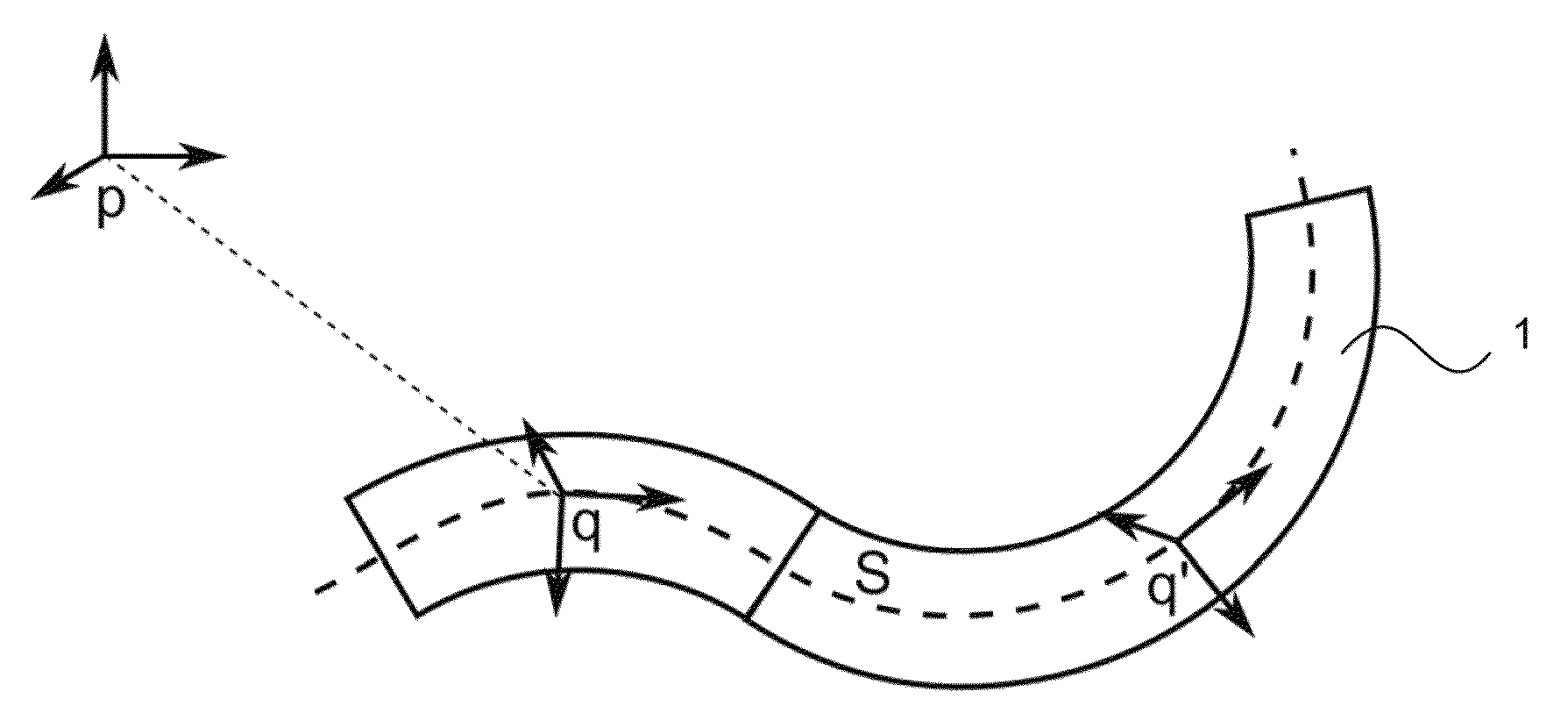
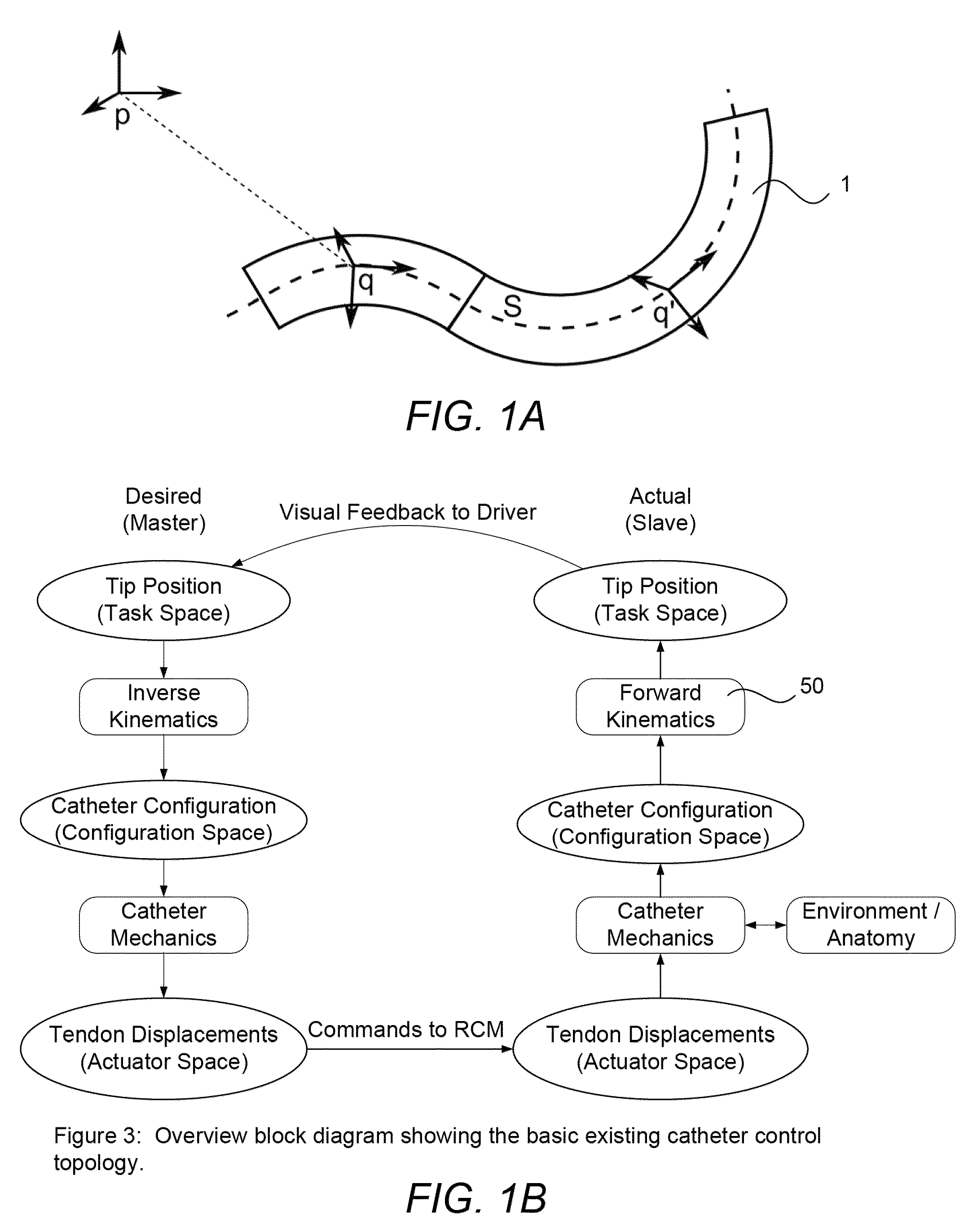
However, such control is subject to error by multiple sources. FIG. 1B shows an example of an overview block diagram of a basic topology used for controlling devices without shape feedback.
These mathematical operations are essentially inverted by the physical system in actuating the device, subject to disturbances such as interference with the environment.
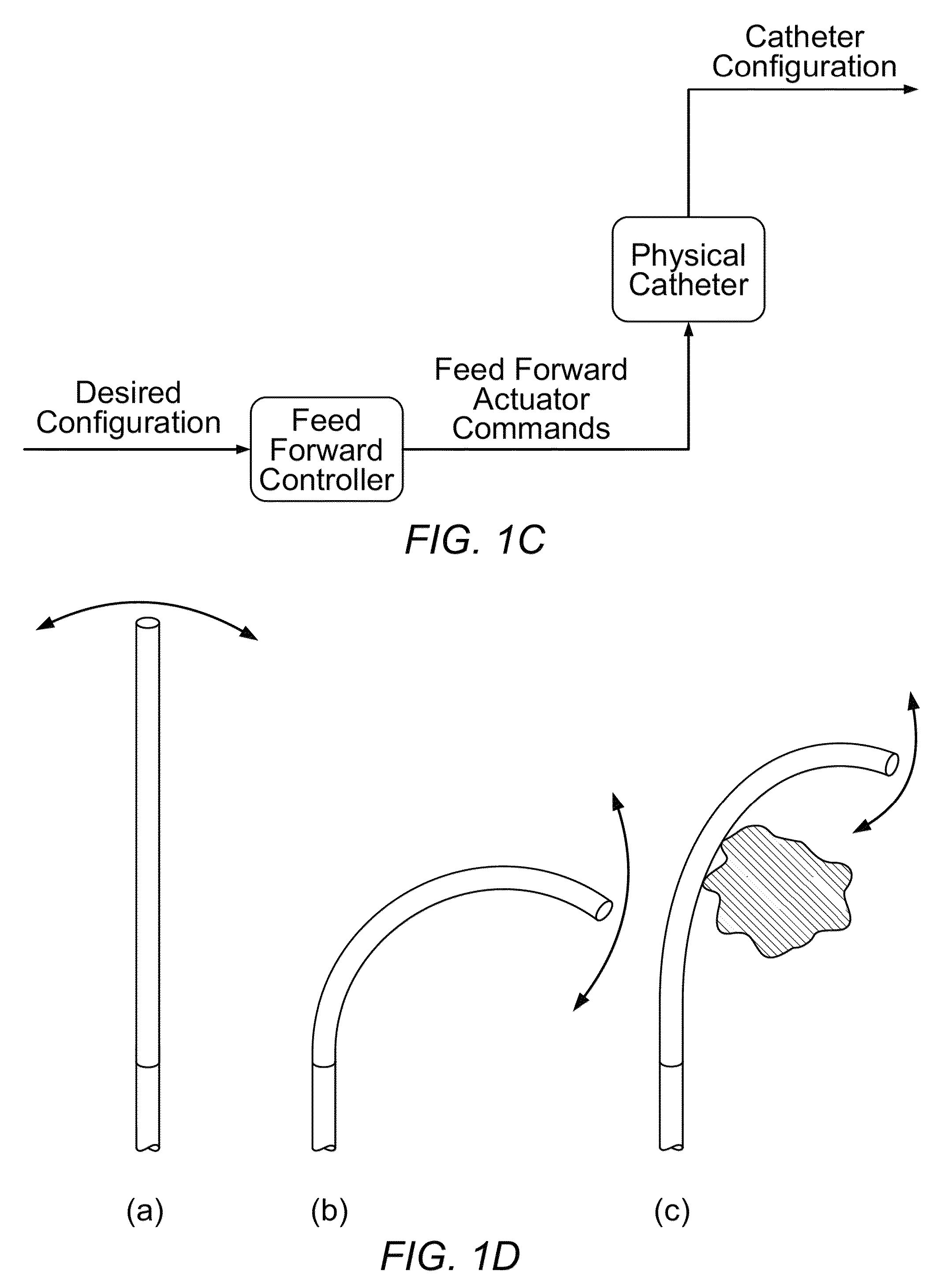
However, there are numerous reasons why the assumed motion of the catheter will not match the actual motion of the catheter, one important factor is the presence of unanticipated or unmodeled constraints imposed by the patient's anatomy.
Clearly, the presence of unanticipated or unmodeled portions of the anatomy affects the behavior and therefore kinematics of the shapeable instrument.
However, the presence of modeling inaccuracies and environment interaction causes a differential between the actual position from that intended.
Conventional technologies such as electromagnetic position sensors, available from providers such as the Biosense Webster division of Johnson & Johnson, Inc., can be utilized to measure 3-dimensional spatial position but may be limited in utility for elongate medical instrument applications due to hardware geometric constraints, electromagnetivity issues, etc.

Method used


Image

  • Fiber optic instrument sensing system
  • Fiber optic instrument sensing system
  • Fiber optic instrument sensing system

Examples


Embodiment Construction

[0124]Referring to FIG. 2A, a conventional manually-steerable catheter (1) is depicted. Pullwires (2) may be selectively tensioned through manipulation of a handle (3) on the proximal portion of the catheter structure to make a more flexible distal portion (5) of the catheter bend or steer controllably. The handle (3) may be coupled, rotatably or slidably, for example, to a proximal catheter structure (34) which may be configured to be held in the hand, and may be coupled to the elongate portion (35) of the catheter (1). A more proximal, and conventionally less steerable, portion (4) of the catheter may be configured to be compliant to loads from surrounding tissues (for example, to facilitate passing the catheter, including portions of the proximal portion, through tortuous pathways such as those formed by the blood vessels), yet less steerable as compared with the distal portion (5).

[0125]Referring to FIG. 2B, a robotically-driven steerable catheter (6), has some similarities with...


PUM


Abstract

Systems are described herein that improve control of a shapeable or steerable instrument using shape data. Additional systems use such shape data for improved mapping or adjusting models of the instrument. Such systems include robotic medical systems for controlling a shapeable instrument within an anatomical region having a controller, one or more actuators, and a localization system for guiding one or more shapeable instruments.

Description

FIELD OF THE INVENTION[0001]The invention relates generally to medical instruments, such as elongate steerable instruments for minimally-invasive intervention or diagnosis, and more particularly to a method, system, and apparatus for sensing or measuring the shape or position and shape of one or more parts of a shapeable elongate medical instrument.BACKGROUND[0002]Currently known minimally invasive procedures for diagnosis and treatment of medical conditions use shapeable instruments, such as steerable devices, flexible catheters or more rigid arms or shafts, to approach and address various tissue structures within the body. Hereafter, such devices are referred to as “shapeable” instruments. Such a term can include steerable devices, flexible devices, devices having one or more pre-determined shapes (such as an articulating device that locks into a particular shape). For various reasons, it is highly valuable to be able to determine the 3-dimensional spatial position of portions of ...

Claims


Application Information

Patent Timeline
Patent Type & Authority Patents(United States)
IPC IPC(8): A61M31/00
CPCA61B1/00149A61B1/00165A61B1/008A61B19/2203A61M25/0133A61B2017/003A61B2019/2211A61B2019/2223A61B2019/2246A61B2019/2276A61B2019/2284A61B2019/2292A61B2019/502A61B2019/5253A61B2019/5259A61B2019/5261A61B2017/00477A61B2034/715A61B2034/742A61B2034/744A61B2034/102A61B2034/2053A61B2034/301A61B34/30A61B34/37A61B34/76A61B2034/2059A61B2034/2061A61B1/009
Inventor ROELLE, MATTHEW J.TANNER, NEAL A.YOUNGE, ROBERT G.CARLSON, CHRISTOPHERBARBAGLI, FEDERICOCAMARILLO, DAVID
Owner AURIS HEALTH INC
Learn More