Method for manufacturing electrolytic capacitor with electrically conductive solid layer and electrolytic capacitor with electrically conductive solid layer

a technology of electrolytic capacitors and solid layers, applied in the manufacture of electrolytic capacitors, electrolytic capacitors, capacitor details, etc., can solve the problems of increasing leakage current and the inability to repair the action described above, and achieves excellent safety and hardly causes short circuit

Active Publication Date: 2013-06-11
SANYO ELECTRIC CO LTD +1
View PDF26 Cites 33 Cited by
  • Summary
  • Abstract
  • Description
  • Claims
  • Application Information

AI Technical Summary

Benefits of technology

[0012]In order to solve the above-mentioned problem, an object of the invention is to provide an electrolytic capacitor hardly causing short circuit and excellent in safety even if an overvoltage is applied.
[0021]According to the present invention, an electrolytic capacitor hardly causing short circuit and excellent in safety can be produced even if an overvoltage is applied.

Problems solved by technology

However, with respect to the solid electrolytic capacitor described above, since an electrically conductive solid polymer having low repairability of a dielectric layer as an electrolyte is employed, the leak current tends to increase.
On the other hand, in a case of a solid electrolytic capacitor in which an electrically conductive solid layer is formed, since essentially no ionic migration occurs, the repair action as described above can scarcely be expected.

Method used


Image

  • Method for manufacturing electrolytic capacitor with electrically conductive solid layer and electrolytic capacitor with electrically conductive solid layer
  • Method for manufacturing electrolytic capacitor with electrically conductive solid layer and electrolytic capacitor with electrically conductive solid layer
  • Method for manufacturing electrolytic capacitor with electrically conductive solid layer and electrolytic capacitor with electrically conductive solid layer

Examples


example 1

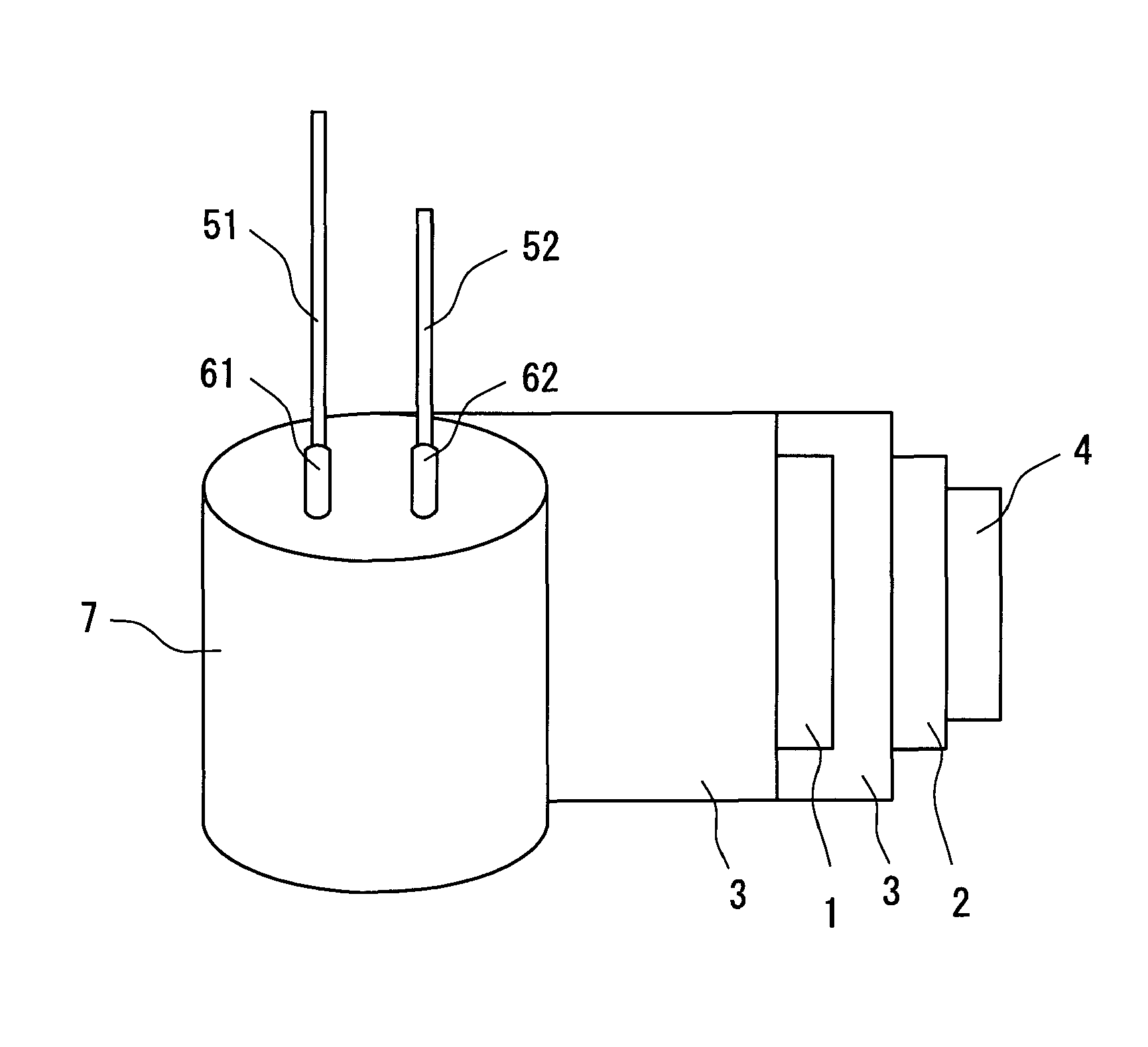
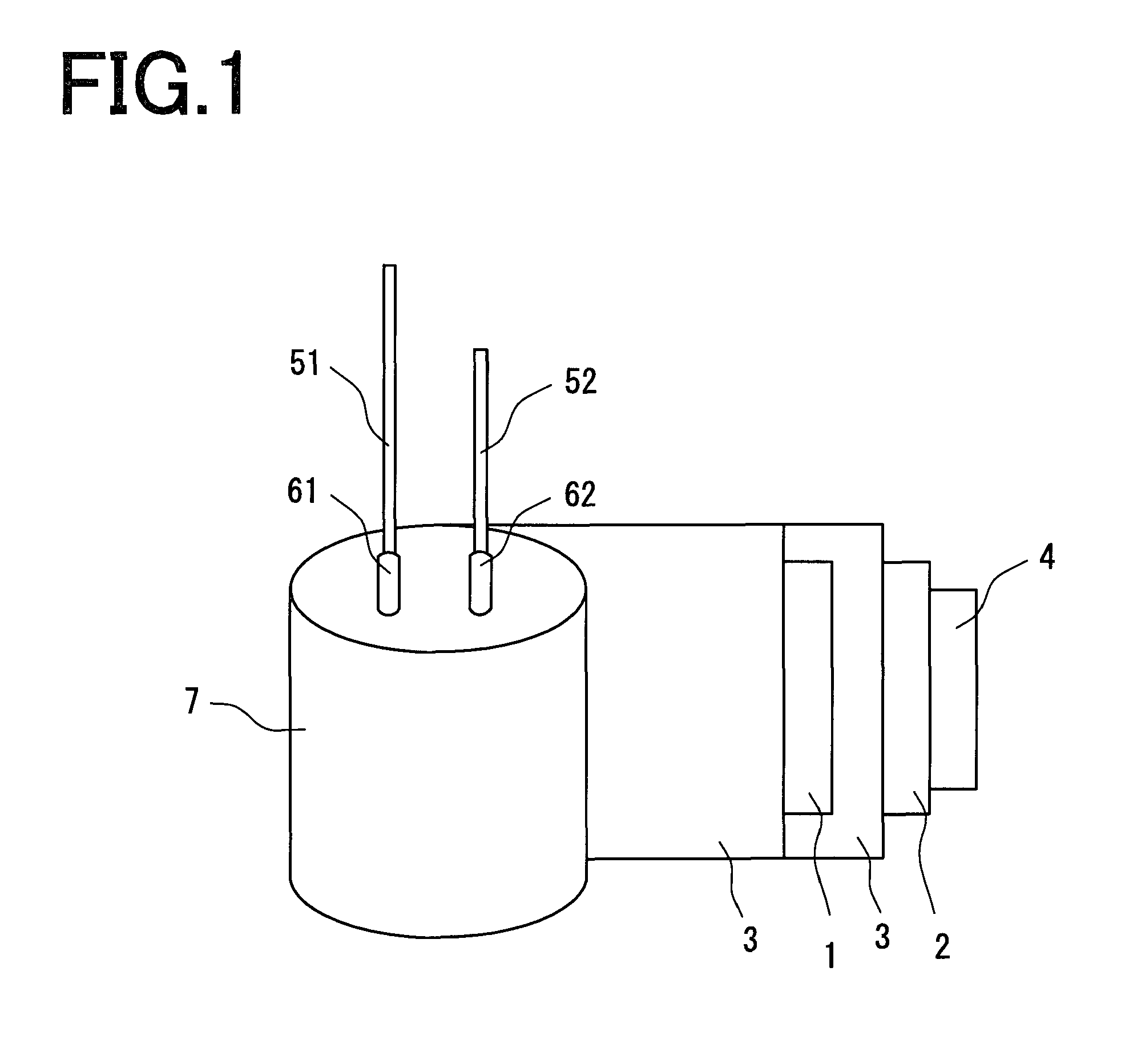
[0046]An anode foil having a dielectric layer thereon and an opposite cathode foil were wound with a separator interposed therebetween, whereby a capacitor element which had a dimension in the completed state (the outer dimension of the electrolytic capacitor in the state where the capacitor element is housed in an aluminum casing) of diameter 10 mm×height 10.5 mm, and which had a rated voltage of 4 V and a nominal capacitance of 1200 μF, was produced. Next, the capacitor element produced in the above-mentioned manner was impregnated with a dispersion solution prepared by dispersing polyethylenedioxythiophene particles containing a dopant agent in water (concentration of polyethylenedioxythiophene: 10% by weight), at 25° C. for 1 minute under reduced pressure of 89 kPa. After the impregnation, the capacitor element was taken out of the dispersion solution, put in a drying oven at 125° C. and dried to form an electrically conductive solid layer. Next, the capacitor element in which t...

example 2

[0048]An electrolytic capacitor was produced in the same manner as in Example 1, except that sulfolane was used instead of γ-butyrolactone.


PUM

PropertyMeasurementUnit
thicknessaaaaaaaaaa
thicknessaaaaaaaaaa
pressureaaaaaaaaaa

Abstract

A method for manufacturing an electrolytic capacitor including: forming a capacitor element having an anode foil and a cathode foil; impregnating the capacitor element with a dispersion solution containing particles of an electrically conductive solid or aggregates thereof and a dispersion solvent to form an electrically conductive solid layer having the particles of the electrically conductive solid or the aggregates thereof in the capacitor element ; and impregnating the capacitor element having the electrically conductive solid layer with a solvent containing no supporting salt.

Description

RELATED CASE[0001]The present application is related to the U.S. patent application Ser. No. 12 / 168,489, entitled “METHOD FOR MANUFACTURING ELECTROLYTIC CAPACITOR AND ELECTROLYTIC CAPACITOR,” filed Jul. 7, 2008, which is commonly assigned to the same assignees of the present application and which claims a priority based on Japanese Patent Application No. 2007-180383 filed Jul. 9, 2007, all of which are hereby incorporated by reference in their entirely.BACKGROUND OF THE INVENTION[0002]1. Field of the Invention[0003]The invention relates to an electrolytic capacitor including an electrically conductive solid layer formed in a capacitor element having an anode foil and a cathode foil.[0004]2. Description of the Related Art[0005]As digitization of electronic equipment proceeds, it has become required that capacitors used therefor have a smaller size, a larger capacitance and a lower Equivalent Series Resistance (hereinafter, referred to as “ESR”) in a high-frequency range.[0006]In orde...

Claims


Application Information

Patent Timeline
Patent Type & Authority Patents(United States)
IPC IPC(8): H01G9/02H01G9/00H01G9/15H01G11/56
CPCH01G9/0036H01G9/028H01G9/151H01G11/56H01G11/48H01G9/15Y10T29/417Y02E60/13
Inventor KAKUMA, KENJIHOSOGI, MASAKAZUYAMASHITA, JUNICHITAKETANI, YUTAKAOKUDA, HIROYUKIISHIHARA, KOSO
Owner SANYO ELECTRIC CO LTD
Why Eureka
Try Eureka