Plug valve indicator

a technology of indicator and valve valve, which is applied in the direction of valve operating means/releasing devices, service pipe systems, transportation and packaging, etc., can solve the problem that the hand wheel rotation of the hand wheel can require considerable force to achieve high fluid pressure within the valv

Inactive Publication Date: 2013-06-18
WEIR SPM
View PDF21 Cites 22 Cited by
  • Summary
  • Abstract
  • Description
  • Claims
  • Application Information

AI Technical Summary

Problems solved by technology

High fluid pressure within the valve can require considerable force to rotate the hand wheel.

Method used


Image

  • Plug valve indicator
  • Plug valve indicator
  • Plug valve indicator

Examples


Embodiment Construction

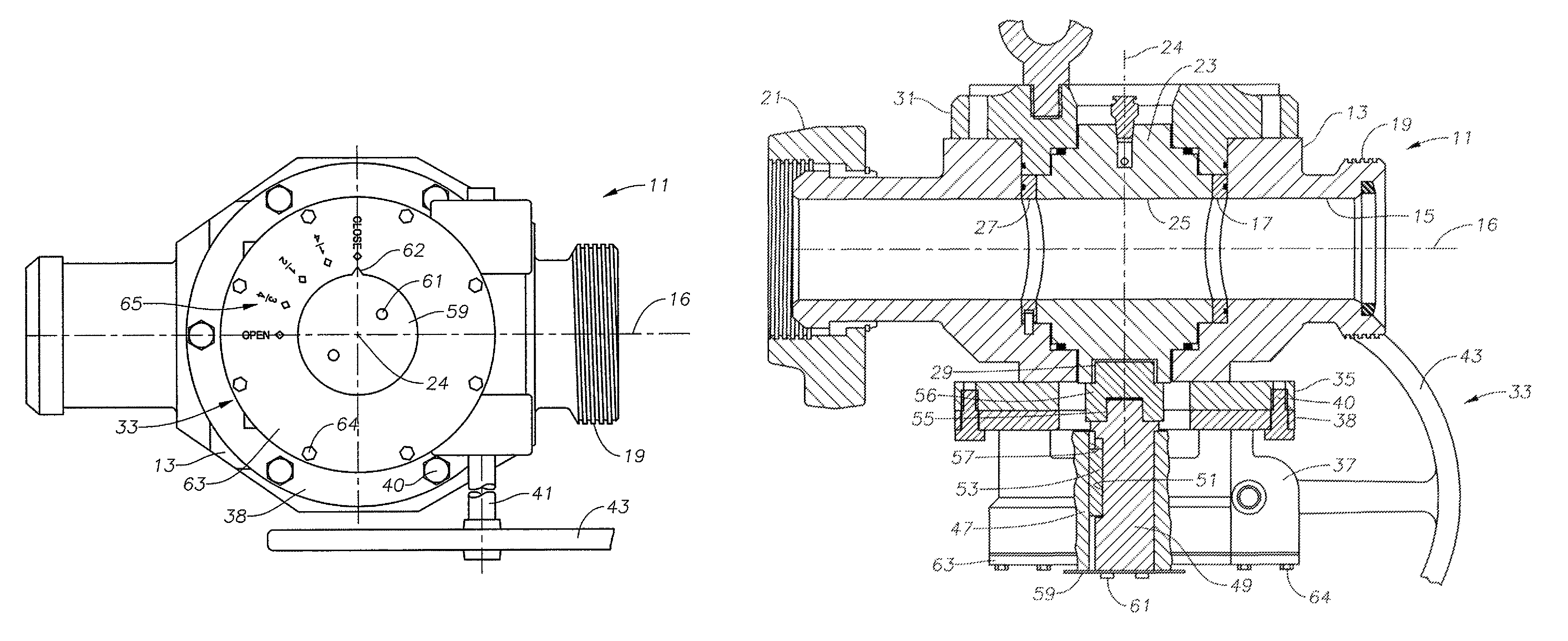
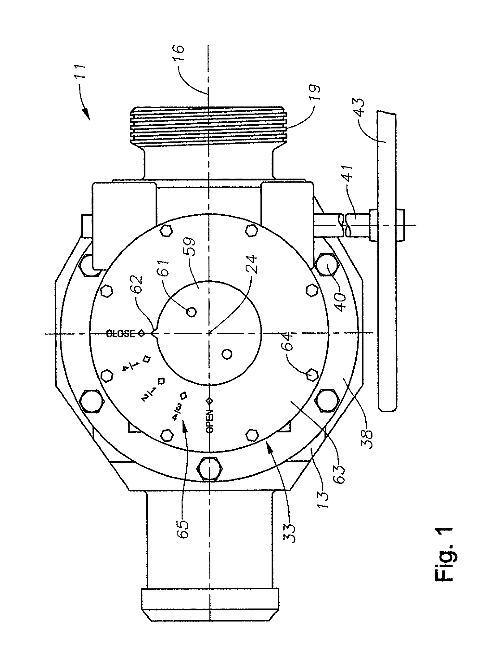
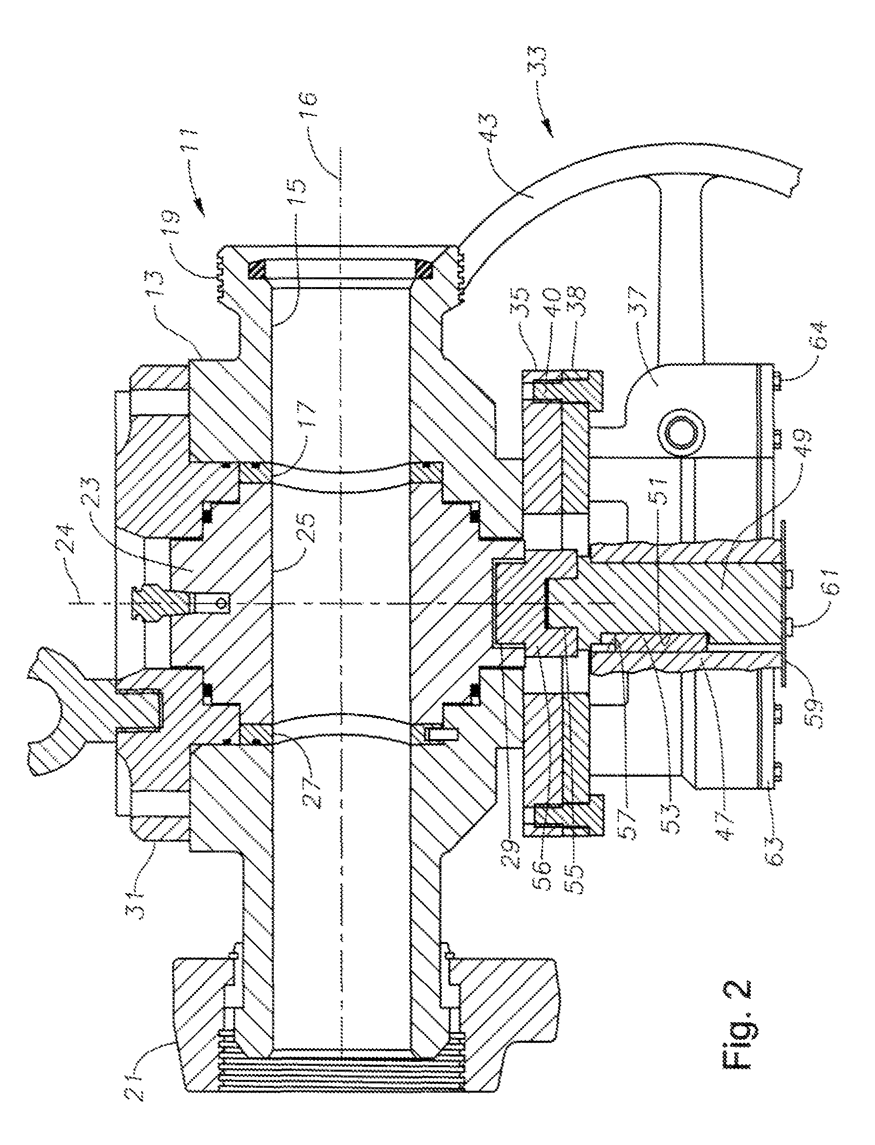
[0018]Referring to FIG. 2, in this example, valve 11 is shown as a plug valve. Valve 11 has a body 13 with a flow passage 15 extending through it along an axis 16. A cavity 17 is located in the central portion of flow passage 15. In this example, cavity 17 is cylindrical. Flow passage 15 has opposite ends for securing into a flow line. The ends may be configured in any suitable manner, and in this embodiment, external threads 19 are located on one end and a rotatable coupling sleeve 21 on the other.

[0019]A rotatable, cylindrical plug or valve element 23 is located within cylindrical cavity 17. Valve element 23 is a cylindrical member that is rotatable about an axis 24 that is perpendicular to axis 16 of flow passage 15. Valve element 23 has a passage 25 that extends from one side to the other. When in the open position, passage 25 is coaxial with flow passage 15. When in the closed position, passage 25 is perpendicular to flow passage 15, blocking flow through passage 15. Valve elem...


PUM


Abstract

A valve has a body having a rotatable valve element. A drive mechanism has a drive input member and a drive output member that are coupled to the valve element for rotating the valve element. A shear member is operatively located within the drive mechanism between the drive input member and the drive output member for shearing in the event the force to rotate the valve element is excessive. The valve has indicia indicating open and closed positions for the valve element. An indicator is mounted to output drive member to properly align with the indicia regardless whether the shear member has sheared or not.

Description

CROSS-REFERENCE TO RELATED APPLICATION[0001]This application claims priority to provisional application Ser. No. 61 / 183,617, filed Jun. 3, 2009.FIELD OF THE INVENTION[0002]This invention relates in general to plug valves for flowlines and in particular to an indicator that indicates the position of the plug.BACKGROUND OF THE INVENTION[0003]In hydraulic fracturing of wells, large pumps are connected to a wellhead by temporary flow lines to pump high volumes of fluid into the well. The pressure is selected to be high enough to cause cracks or fracturing of the earth formation. Valves are employed in the flow lines to control the flow.[0004]One type of valve has a body with a flow passage extending through it that intersects a central cavity. A rotatable valve element, such as a cylindrical plug, is mounted in the cavity. The valve element has a passage that aligns with the passage in the body when open. A drive mechanism is used to rotate the valve element between open and closed posi...

Claims


Application Information

Patent Timeline
Patent Type & Authority Patents(United States)
IPC IPC(8): F16K35/00
CPCF16K5/0442F16K37/0016F16K37/0008Y10T137/8292
Inventor WITKOWSKI, BRIAN C.KOTAPISH, EDWARD C.
Owner WEIR SPM
Why Eureka
Try Eureka