Screen and screen element

a screen element and screen technology, applied in the field of screen elements, can solve the problems of increasing the dead surface of the screen element, reducing the number of supporting points to a minimum, not being a convenient alternative, and high operating expenses, so as to improve the screening efficiency and safety. the effect of holding and giving the screen additional stability

Active Publication Date: 2013-06-25
METSO OUTOTEC (FINLAND) OY
View PDF25 Cites 6 Cited by
  • Summary
  • Abstract
  • Description
  • Claims
  • Application Information

AI Technical Summary

Benefits of technology

[0011]The transverse sides of the inventive screen element are provided with at least one projection and / or at least one recess. As a result, neighbouring screen elements can engage each other lockingly in a direction transversely to the plane of the screen element. Neighbouring elements are thus held together in the vertical direction and the risk of forming gaps between the short sides of neighbouring screen elements is reduced, which in turn reduces the need for a support frame in the transverse direction.
[0028]According to a characteristic feature, said at least one projection and / or recess on the longitudinal sides and the transverse sides, respectively, are arranged so that the screen element when rotated half a turn about an axis in the normal direction of the screen surface has the same circumferential shape. This property increases the flexibility and cost-efficiency of the screen since local wear on an individual screen element can be alleviated by turning of the individual screen element.

Problems solved by technology

The active surface is normally limited by the rigidity of the screen element since a screen element of lower strength requires supporting sections arranged at shorter intervals, which results in an increased dead surface of the screen element.
Nevertheless, letting the entire screening surface consist of a single screen element and reducing the number of supporting points to a minimum does not constitute a convenient alternative.
Such a method would certainly provide a maximum surface, but at the price of very high operating expenses since it would be necessary to exchange the entire screen deck also in case of local wear.

Method used


Image

  • Screen and screen element
  • Screen and screen element
  • Screen and screen element

Examples


first embodiment

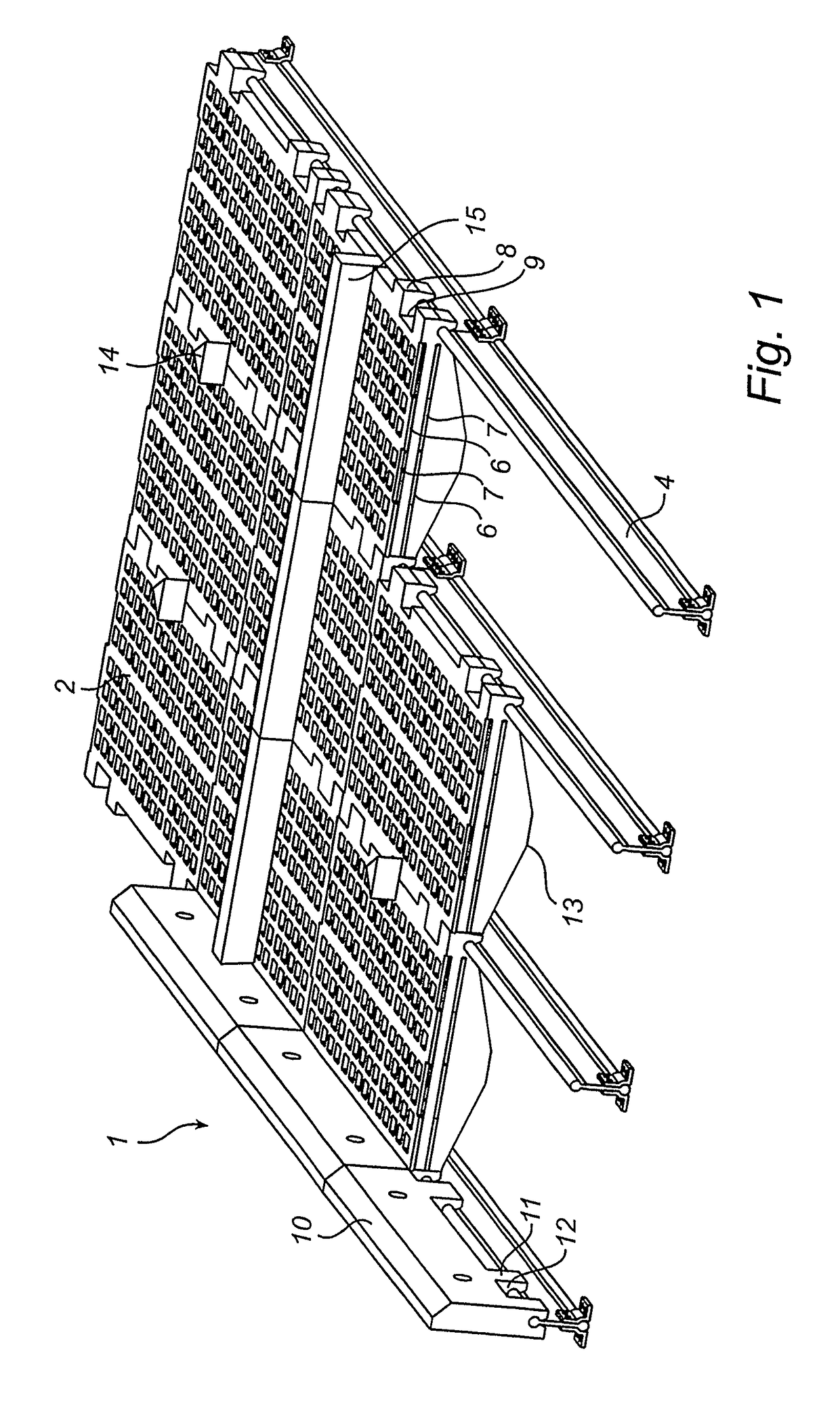
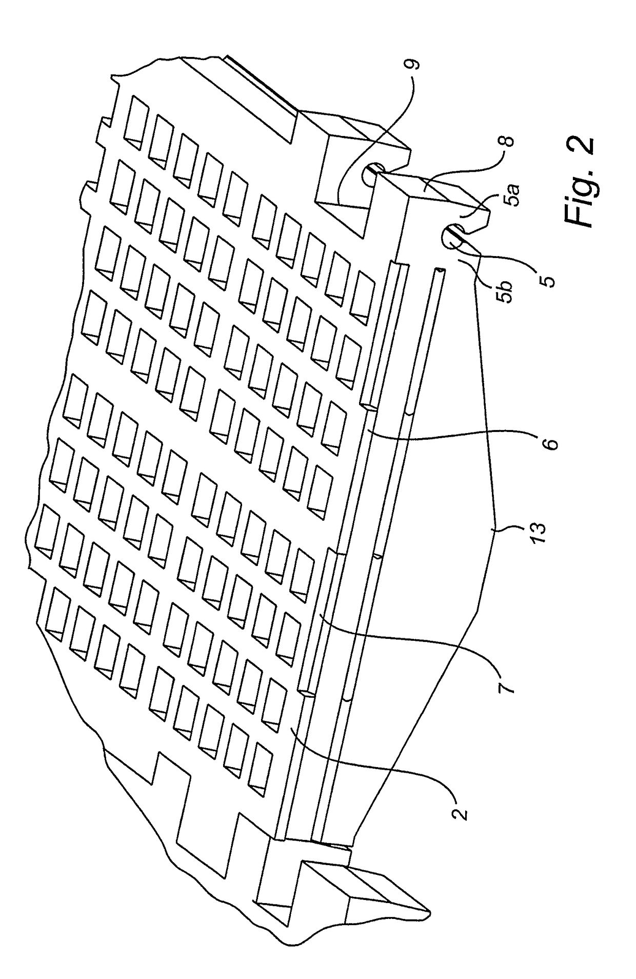
[0040]In this first embodiment, the screen element 2 has on its underside cambers 13 to increase its rigidity.

[0041]The screen frame wall guard 10, which is screwed to the screen frame wall (not shown), has projections 11 and recesses 12 which engage the projections 8 and the recesses 9 on the outer long sides of the transversely outermost screen elements 8, thereby locking these screen elements and thus also the entire screening surface. The snap locking and the locking engagement prevent the screening surface from being moved, either transversely or longitudinally.

[0042]Deflectors 14 and blocking strips 15 are mounted in recesses formed on the screen 1 in the screen elements 2.

[0043]FIGS. 5a-c show examples of cross-sections of the attachment section 4. The attachment sections used in the screen 1 in FIG. 1 are, as is more clearly to be seen in FIG. 5a, symmetrical so that they are turnable and therefore have a longer life before they need to be exchanged. Also the attachment sect...

second embodiment

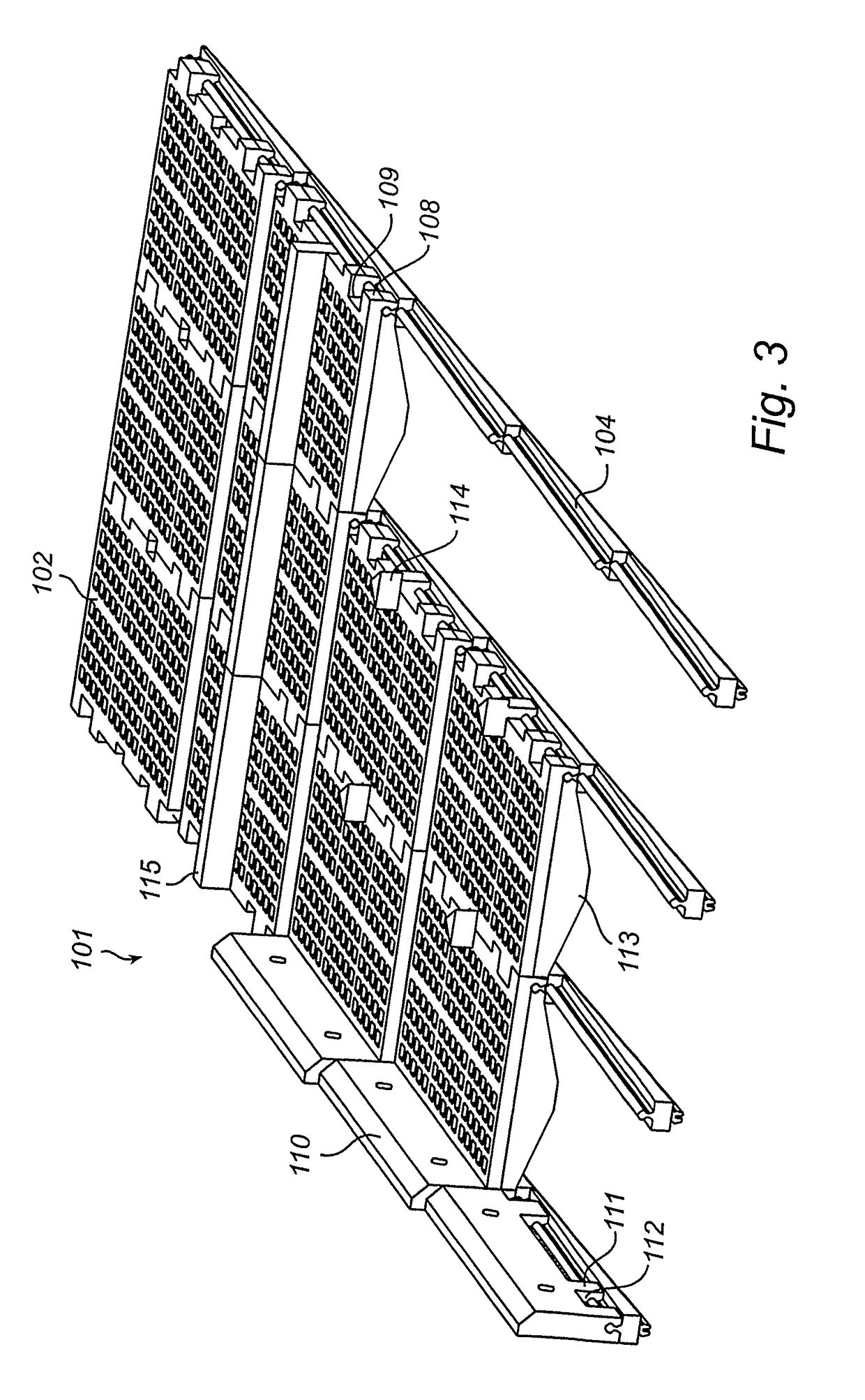
[0044]According to the inventive screen as shown in FIGS. 3 and 4, the attachment sections 104 of the screen 101 are stepped, whereby the screen elements 102 attached to the attachment sections 104 form a stepped screening surface, a so-called step deck. This embodiment is particularly useful in applications involving many fines, since the stepped screening surface turns the material that is being screened and in this manner improves the screening efficiency.

[0045]The projections 106 and the recesses 107 of the screen elements 102 here ensure increased tightness in the joint between successively arranged screen elements 102 compared with prior-art step decks.

[0046]The stepped attachment section 104 ensures an alternative way of providing a step deck. In prior-art step decks, the section has been straight and the screening elements have instead been placed overlapping each other.

[0047]FIGS. 5d-f show examples of cross-sections of the attachment section 104.

[0048]A person skilled in t...


PUM


Abstract

A screen element (2) of a screen (1) has longitudinal sides adapted to be arranged in a longitudinal direction of a screen frame (4) and transverse sides adapted to be arranged in a transverse direction of the screen frame (4). The transverse sides of the screen element (2) are provided with at least one projection (6) and / or at least one recess (7) for locking engagement, in a direction transversely to the plane of the screen element (2), with a corresponding projection (6) and / or recess (7) on neighboring screen elements arranged in the screen frame (4). A screen (1) with a screen element (2) arranged in a screen frame (4) is also disclosed.

Description

FIELD OF THE INVENTION[0001]The present invention relates to a screen element adapted to be arranged in a screen frame, which has longitudinal sides adapted to be arranged in a longitudinal direction of the screen frame and transverse sides adapted to be arranged in a transverse direction of the screen frame. The invention also relates to a screen, which has a screen frame and screen elements arranged in the screen frame, the screen elements having longitudinal sides arranged in a longitudinal direction of the screen frame and transverse sides arranged in a transverse direction of the screen frame.BACKGROUND ART[0002]Screen elements and screens of the above type are known, for instance, from EP-A-26 961 and US-RE 38,303 E which disclose different types of screens with screen elements arranged in a screen frame.[0003]These screens have several advantages compared with those of earlier generations since individual screen elements can be exchanged when worn out, and since this exchange...

Claims


Application Information

Patent Timeline
Patent Type & Authority Patents(United States)
IPC IPC(8): B07B1/46
CPCB07B1/4645B07B2201/02
Inventor GRONVALL, LARSLARSSON, KALLE
Owner METSO OUTOTEC (FINLAND) OY
Why Eureka
Try Eureka