Pushable exercise apparatus for resistance training

Inactive Publication Date: 2013-06-25
MCFEE SUSAN L
View PDF32 Cites 34 Cited by
  • Summary
  • Abstract
  • Description
  • Claims
  • Application Information

AI Technical Summary

Benefits of technology

[0006]Embodiments of the present invention solve the above-mentioned problems and provide a distinct advance in the art of pushable resistance training devices. More particularly, embodiments of the invention provide a pushable apparatus operable to roll along a surface and provide resistance to a user. In preferred embodiments of the invention, the apparatus provides resistance via an electrical braking system, such as a generator braking system.
[0007]The pushable apparatus may comprise a frame, a handle, at least one wheel, a wheel shaft fixedly attached to the wheel and rotatably supported by the frame, and the electrical braking system having a motor driven by the rotation of the wheel shaft and comprising variable electric resistance. For example, a variable resistor may provide varying amounts of electrical resistance to the motor such that an amount of torque required to rotate the wheel when the electrical resistance is small is greater than the amount of torque required to rotate the wheel when the electrical resistance is large.
[0008]The pushable apparatus may further comprise any number of wheels, which may or may not be fixedly attached to the wheel shaft for additional balance and stability of the pushable apparatus. Furthermore, the frame may comprise or be coupled with a user control panel operable to change the amount of electrical

Problems solved by technology

However, applying additional weight to the device requires a user to stop walking or running in order to change the amount of resistance or weight.
Additionally, the resistance provided by the weight in these resistance devices can vary by an undesired or even dangerous amount depending on if the user is going uphill or downhi

Method used


Image

  • Pushable exercise apparatus for resistance training
  • Pushable exercise apparatus for resistance training
  • Pushable exercise apparatus for resistance training

Examples


Embodiment Construction

[0024]The following detailed description of the invention references the accompanying drawings that illustrate specific embodiments in which the invention can be practiced. The embodiments are intended to describe aspects of the invention in sufficient detail to enable those skilled in the art to practice the invention. Other embodiments can be utilized and changes can be made without departing from the scope of the present invention. The following detailed description is, therefore, not to be taken in a limiting sense. The scope of the present invention is defined only by the appended claims, along with the full scope of equivalents to which such claims are entitled.

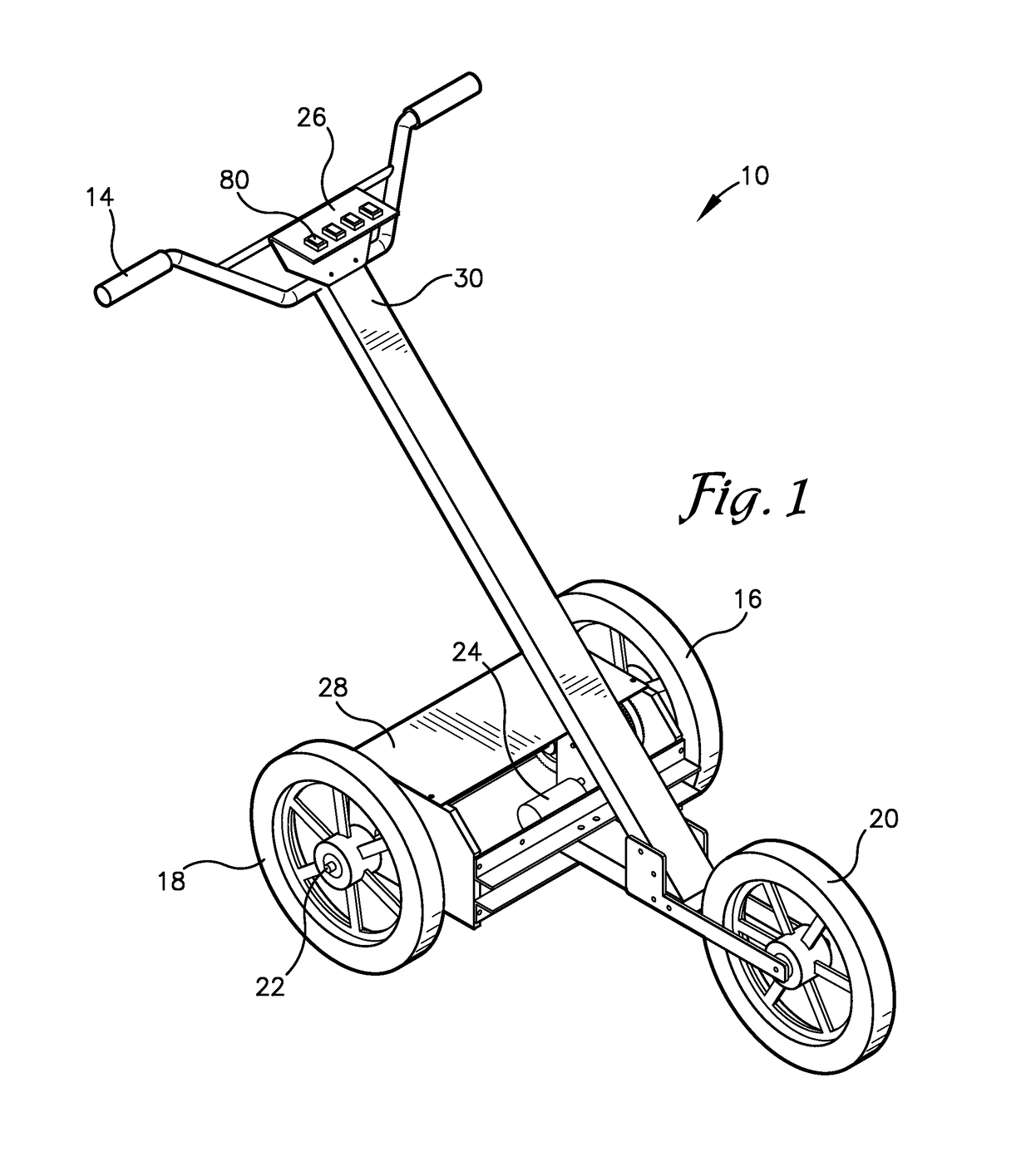
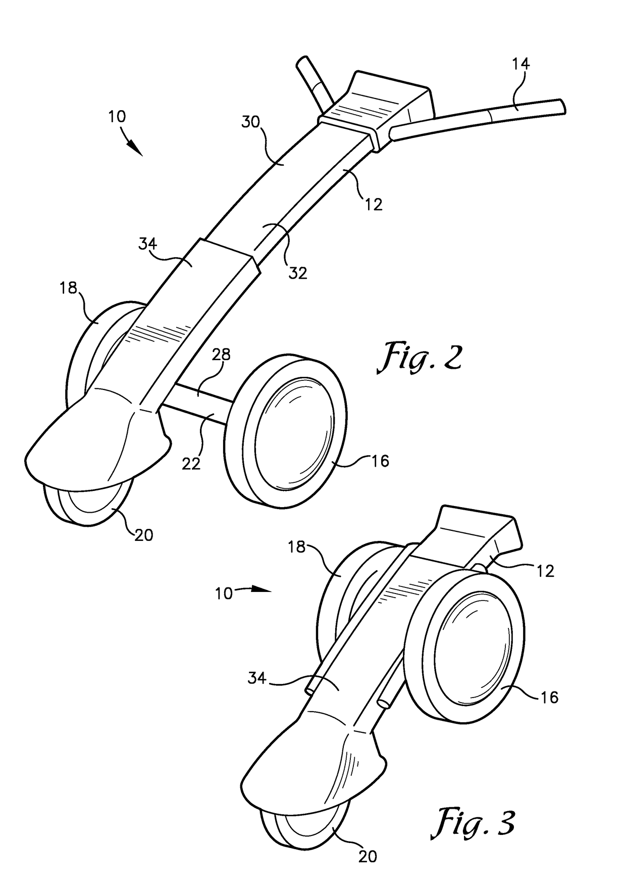
[0025]FIGS. 1 and 2 illustrate embodiments of a pushable exercise apparatus 10 configured for providing varying amounts of resistance to a user pushing the apparatus 10. For example, a user may push the pushable exercise apparatus 10 along any surface such as a road, sidewalk, track, or trail, while walking, running, jo...


PUM


Abstract

A pushable exercise apparatus configured to be pushed along a surface by a user and to provide user-selected variation in resistance to rotation applied to wheels of the apparatus. The apparatus may comprise a frame, a handle, a wheel shaft rotatably supported by the frame, one or more wheels fixedly attached to the wheel shaft, and an electrical braking system, such as a generator braking system. The electrical braking system may have a motor driven by rotation of the wheel shaft and variable electrical resistance such that an amount of torque and/or effort required to rotate at least one of the wheels is dependant on the amount of electrical resistance provided to the motor.

Description

RELATED APPLICATIONS[0001]This nonprovisional patent application claims priority benefit, with regard to all common subject matter, of earlier-filed U.S. provisional patent application titled “Resistance Trainer Exercise Device”, Ser. No. 61 / 090,440, filed Aug. 20, 2008, hereby incorporated by reference in its entirety into the present application.BACKGROUND[0002]1. Field[0003]Embodiments of the present invention relate to resistance training. More particularly, embodiments of the present invention relate to a pushable exercise apparatus with wheels and user-selected variation in torque required to urge the wheels along a surface.[0004]2. Related Art[0005]Various resistance devices or resistance-providing carts exist that allow a user to walk or run while pushing the resistance device. These resistance devices provide various methods to impose load or resistance to increase the torque required to push or pull the resistance device. For example, some resistance devices provide an inc...

Claims


Application Information

Patent Timeline
IPC IPC(8): A63B71/00A63B21/005A63B24/00
CPCA63B69/0028A63B21/0058A63B21/1469A63B23/03583A63B71/0619A63B2225/682A63B2071/0691A63B2210/50A63B2220/12A63B2220/18A63B2220/20A63B2220/30A63B2220/806A63B2220/807A63B2220/808A63B2225/09A63B2225/15A63B2225/50A63B2230/06A63B2230/75A63B2021/0054A63B2021/0059A63B71/0686A63B21/4035A63B21/0054A63B21/0059
Inventor MCFEE, SUSAN L.WICKWAR, RODNEY L.CONNOLLY, JIM
Owner MCFEE SUSAN L
Why Eureka
Try Eureka