Intervertebral prosthetic device

a prosthetic device and intervertebral technology, applied in the field of biocompatible, implantable intervertebral devices for spinal surgery, to achieve the effect of enhancing the distribution of forces

Inactive Publication Date: 2013-06-25
BERTHOLET MAURICE +1
View PDF9 Cites 33 Cited by
  • Summary
  • Abstract
  • Description
  • Claims
  • Application Information

AI Technical Summary

Problems solved by technology

These coverings of the entirety of “implantable parts” with tissue have the drawback of being in direct contact with the bone element of the vertebrae and the lateral or longitudinal movements exerted at this point may induce a friction effect, the short and long-term effects of which in terms of friction-related inflammatory reaction and in terms of particle release with subsequent expulsion of tissue fragments against bone marrow and radices are not foreseeable.

Method used


Image

  • Intervertebral prosthetic device
  • Intervertebral prosthetic device

Examples


Embodiment Construction

)

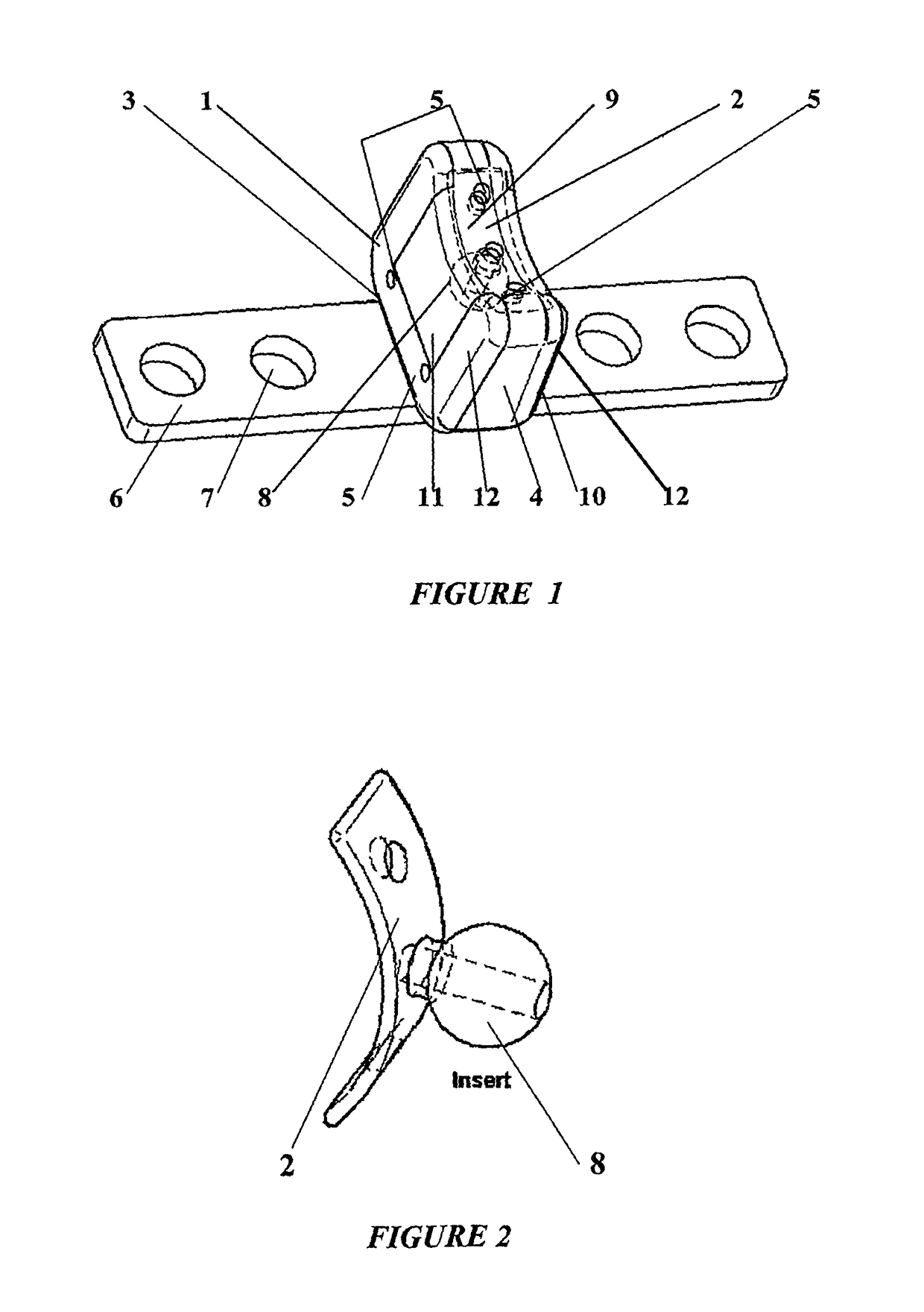
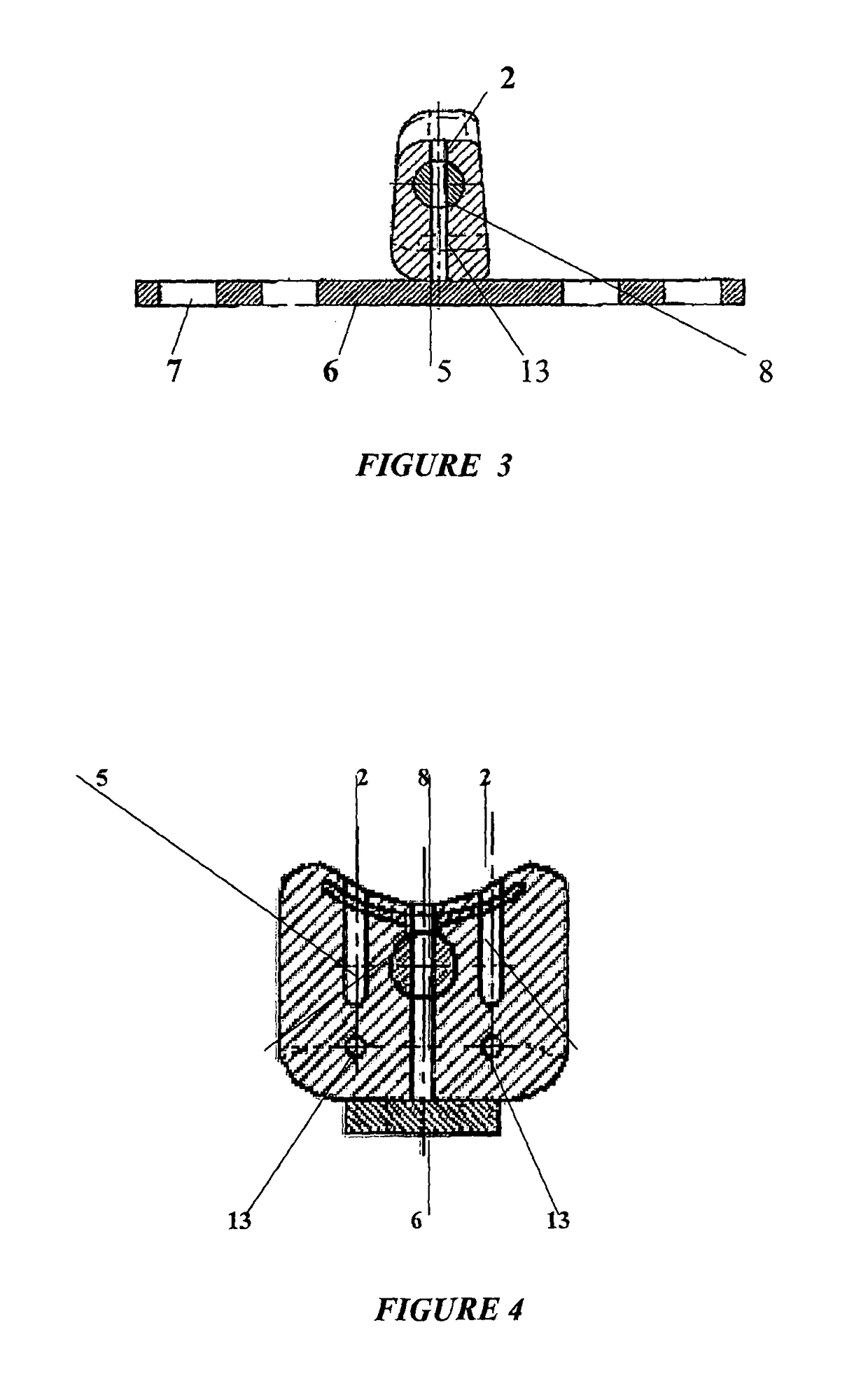
[0012]The part, known as a “shield” (2) necessarily made of rigid material, has a concave shape (FIG. 2) designed to observe the anatomy of the medullary canal against which it is to be positioned. This shield (2) has a protective role during compression or excessive movements, such that there is no silicone creep against the medullary canal under the effect of pressure, liable to give rise to medullary complications due to bone marrow compression and radicular complications due to compression of the radices. It serves as the posterior vertebral ligament generally excised during the surgical procedure and frequently damaged under certain conditions.

[0013]The ball (8) or central core optionally connected to the “shield” (FIG. 2) by a connection member, but always adjoining said shield, is the equivalent of the normal nucleus. It would ideally be positioned in the first third (FIG. 3) of the concave portion (9) of the silicone part so as to be the central axis through which the press...


PUM

PropertyMeasurementUnit
flexibleaaaaaaaaaa
surface featuresaaaaaaaaaa
dimensionsaaaaaaaaaa

Abstract

An intervertebral prosthetic device has a medullary protection shield with a concave shape designed to be adapted to the anatomy of a medullary canal against which the medullary protection shield is able to be positioned, a spherical tough core inside a flexible integral assembly designed for an intervertebral space, and the flexible integral assembly has a truncated parallelepiped shape, wherein a front portion of the truncated parallelepiped shape is higher than a rear portion of the truncated parallelepiped shape, and wherein the rear portion is concave and corresponds to the concave shaped medullary protection shield.

Description

BACKGROUND[0001]The present invention relates generally to a biocompatible, implantable intervertebral device for spinal surgery, with a tough inner part for force distribution and medullary canal protection within a flexible elastomer block, reinforced at the upper and lower ends thereof by a yoke coated with a bone osteoconductive material and provided with an attachment member.[0002]This spinal surgery, and more specifically in the cervical condition in question, is subject to degenerative or accidental phenomena affecting the osteodiscal junctions of the cervical column. Prior procedures made use of total intervertebral disk excision with or without replacement of said disk by a bone graft or substitutes such as coral or cervical cages. These various techniques resulted in definitive stiffening of the two adjacent vertebral segments. This gave rise to the idea of implanting a prosthesis made of biocompatible materials in order to prevent cervical stiffening resulting in long-ter...

Claims


Application Information

Patent Timeline
Patent Type & Authority Patents(United States)
IPC IPC(8): A61F2/44
CPCA61F2/442A61F2002/30016A61F2002/3008A61F2002/30242A61F2002/30448A61F2002/30563A61F2002/30578A61F2002/30616A61F2220/005A61F2230/0071A61F2250/0019A61F2250/0098A61F2310/00796
Inventor BERTHOLET, MAURICEVITTINI, FRANCOIS
Owner BERTHOLET MAURICE
Why Eureka
Try Eureka