Adjustable pulling rod set

a technology of pulling rods and adjustable rods, which is applied in the direction of wing knobs, furniture parts, manufacturing tools, etc., can solve the problems of manufacturing cost and difficulty in assembling/repairing

Active Publication Date: 2013-07-02
GREAT TAIWAN MATERIAL HANDLING
View PDF11 Cites 36 Cited by
  • Summary
  • Abstract
  • Description
  • Claims
  • Application Information

AI Technical Summary

Benefits of technology

[0009]The main objective of the present invention is to provide an improved adjustable pulling rod set for loaders.

Problems solved by technology

However, the complexity of the conventional handlebar arise the cost of manufacturing and the difficulties of assembling / repairing.

Method used


Image

  • Adjustable pulling rod set
  • Adjustable pulling rod set
  • Adjustable pulling rod set

Examples


Embodiment Construction

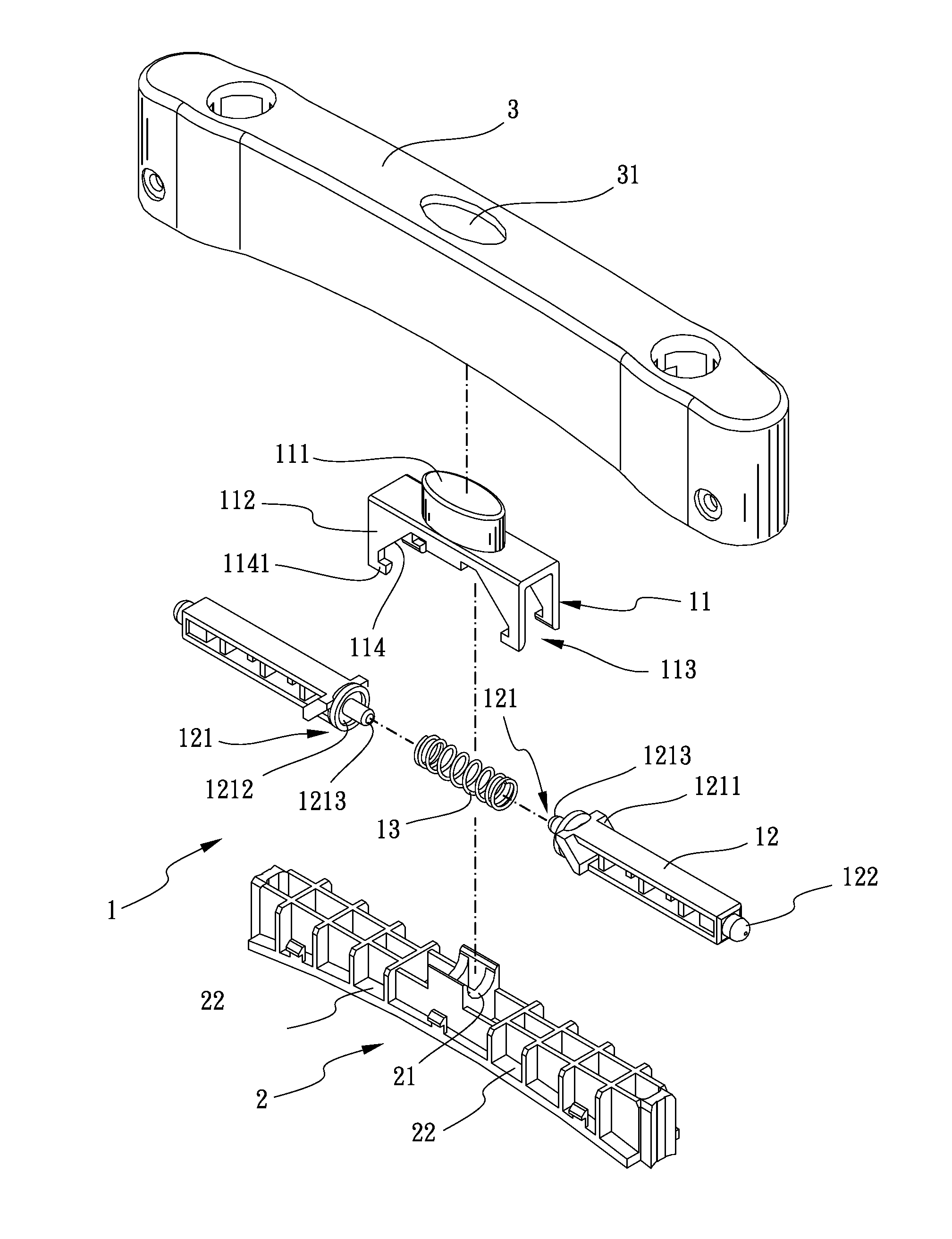
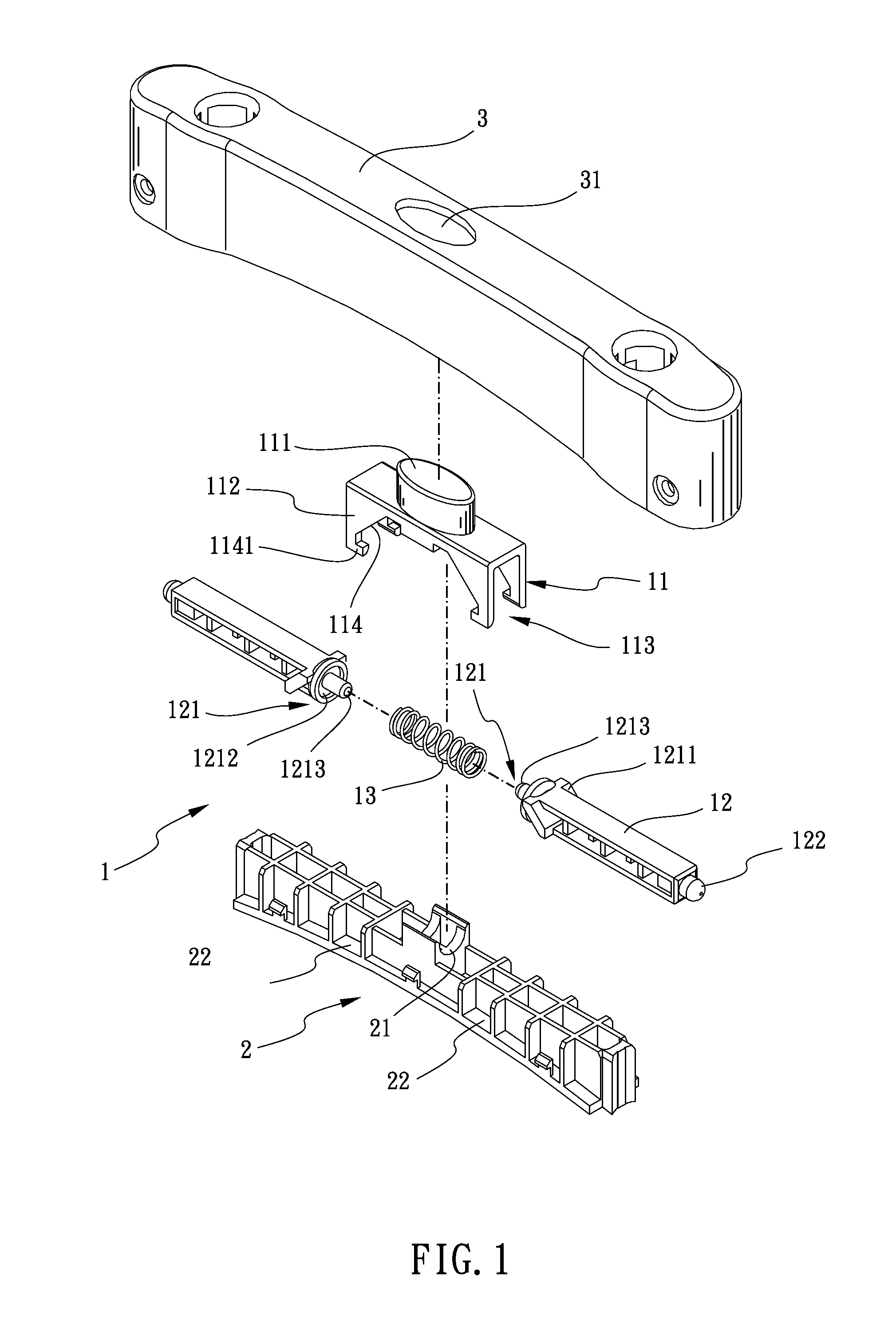
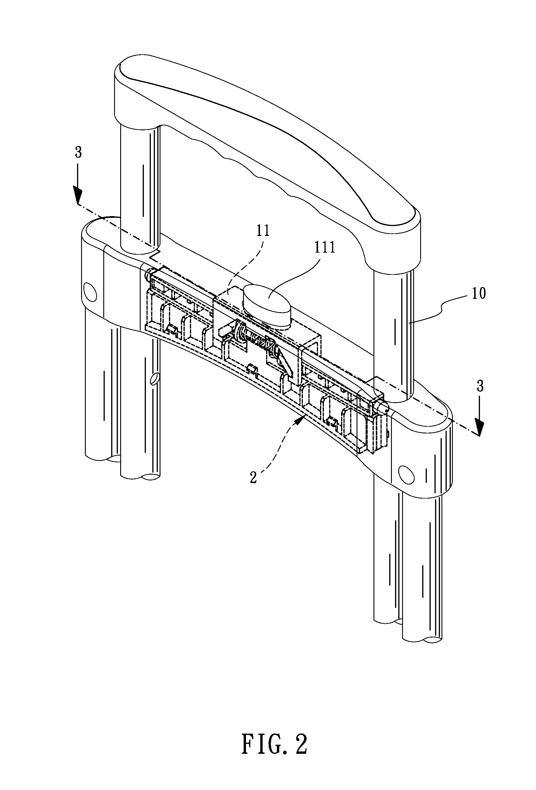
[0019]Referring to the drawings and initially to FIGS. 1-3, an adjustable pulling rod set in accordance with the present invention comprises two pulling rods 10 which are parallel to each other, a switch 1, a base 2 and a cover 3. The two pulling rods 10 pass through the adjustable pulling rod set.

[0020]The switch 1 is mounted on the base 2. The switch 1 includes an operating component 11, two positioning rods 12 and a spring 13. A button 111 is protruded from one side of the operating component 11 and another side of the operating component 11 has two slice bodies 112 extended therefrom. The two slice bodies 112 are parallel to each other. A rail 113 is formed between the two slice bodies 112. Two gaps 114 are respectively opened on the two slice bodies 112. The width of each gap 114 is gradually increased from the button 111 to the bottom of each gap 114 (The top of the gap 114 is narrower and the bottom of the gap 114 is broader as illustrated in FIG. 1). Two feet 1141 are inward...


PUM


Abstract

An adjustable pulling rod set includes a switch, a base and a cover. The switch is on the base. The switch includes an operating component, two positioning rods and a spring. A rail and two gaps are opened on the operating component. The two gaps communicate with the rail. The two positioning rods pass through the rail respectively. Two abutting nodes are defined on one end of the two positioning rods respectively. Each abutting node has two wings. The two wings abut against the inner side of the two gaps. Both ends of the spring abut against the two abutting nodes of the two positioning rods respectively. When the button is pressed, the two wings are forced by the two slice bodies along the two gaps and the two positioning rods compress the spring. Thus, the height of a pulling rod will be adjustable.

Description

BACKGROUND OF THE INVENTION[0001]1. Field of the Invention[0002]The present invention relates to a handlebar for loaders, and more particularly to an adjustable pulling rod set for loaders.[0003]2. Description of Related Art[0004]Generally, a wheel set is mounted on the bottom of loaders, like carts, school bags, baggage in order to reduce the effort and time consumed in transporting the loads or carrying the books, packages. For example, during the delivering process, the post officers can stack more packages on the cart for time saving. In addition, the post officers can transport the heavy packages easily via the wheel set mounted on those loaders.[0005]Conventionally, a loader has a handlebar. Thus, a user can transport the cargos and control the direction of the loader more easily. Otherwise, the user cannot change the direction of the loader easily.[0006]The conventional handlebar has a cap which has a recess and a passing hole defined thereon. A pushing component is assembled...

Claims


Application Information

Patent Timeline
Patent Type & Authority Patents(United States)
IPC IPC(8): A45C7/00
CPCA45C13/262Y10T16/451A45C2013/267
Inventor YANG, CHENG-CHIANG
Owner GREAT TAIWAN MATERIAL HANDLING
Why Eureka
Try Eureka