Method and device for controlling a hydraulic drive system

a hydraulic drive and control method technology, applied in the direction of belt/chain/gearing, mechanical equipment, gear control, etc., can solve the problems of instability of the drive system and/or undesired output parameters

Inactive Publication Date: 2013-07-09
LIEBHERR WERK NENZING
View PDF29 Cites 1 Cited by
  • Summary
  • Abstract
  • Description
  • Claims
  • Application Information

AI Technical Summary

Benefits of technology

[0005]Thus, a control is proposed, whose principle is based on the fact that the actuating signals, which are determined for the individual hydraulic components on the basis of the desired output parameters, are limited or reduced by checking power specifications, which can be specified externally or internally, to thereby ensure the stability of the system. The actuating signals generated are limited or reduced such that the power produced by the hydraulic system and / or the power recirculated to the hydraulic system does not exceed the power specifications. In accordance with the invention, the actuating signal is limited and / or reduced by a superordinate control module in dependence on a matching of a specified power value with a current power value of the hydraulic pump and / or the hydraulic motor. Thereby, too fast and / or too large actuating movements of the actuators of the hydraulic components can be prevented, which would lead to instabilities of the drive system and / or to undesired output parameters.

Problems solved by technology

Thereby, too fast and / or too large actuating movements of the actuators of the hydraulic components can be prevented, which would lead to instabilities of the drive system and / or to undesired output parameters.

Method used


Image

  • Method and device for controlling a hydraulic drive system
  • Method and device for controlling a hydraulic drive system

Examples


Embodiment Construction

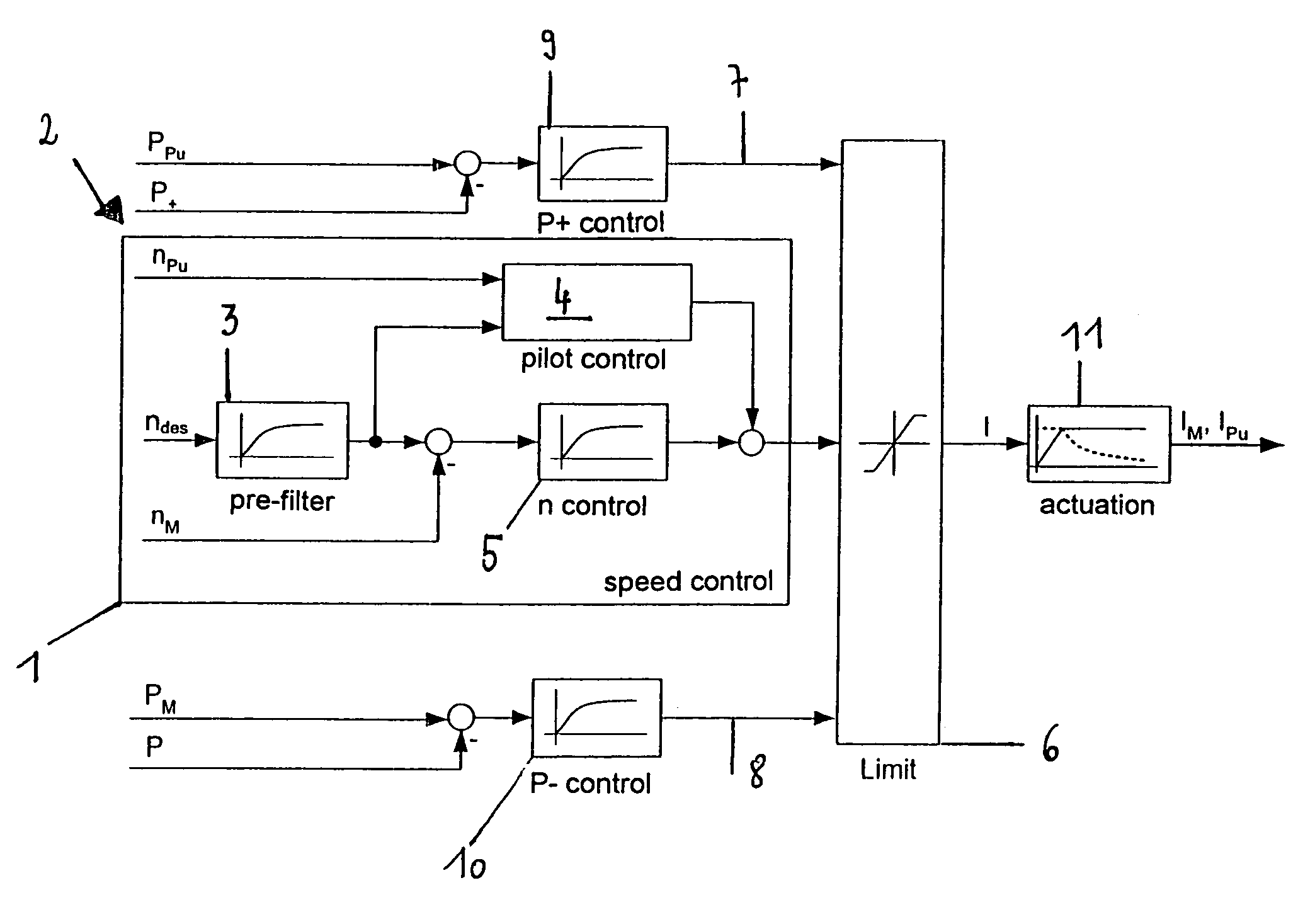
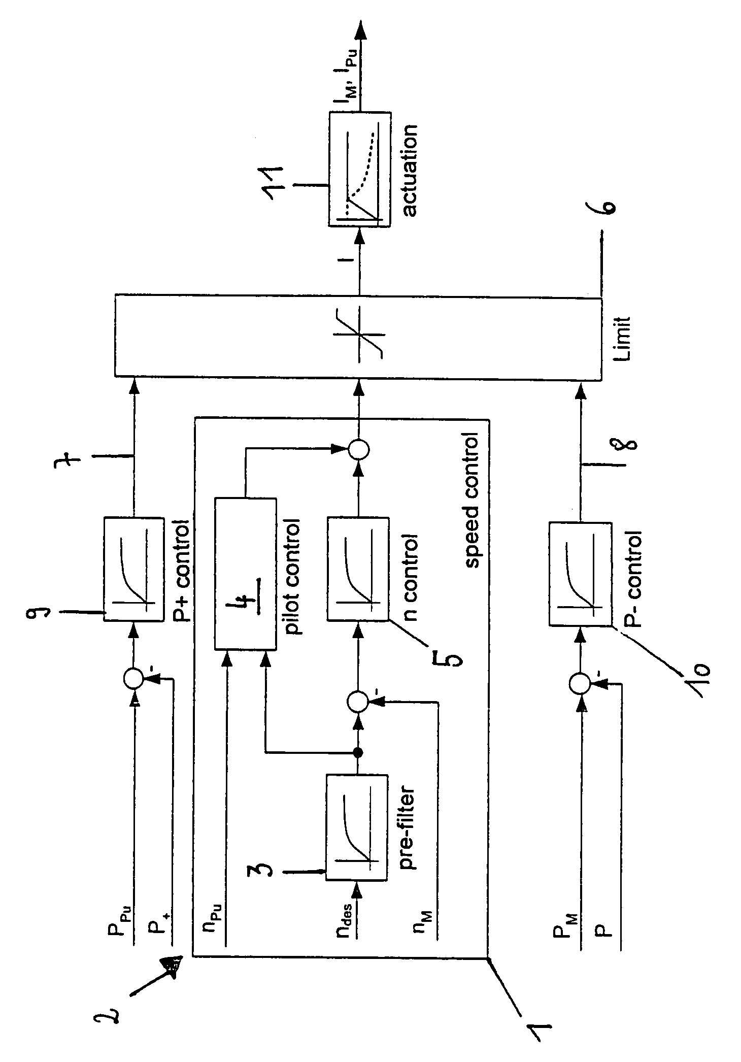
[0020]The control circuit portion 1 of the control device 2 as shown in FIG. 1 serves to generate a dimensionless actuating signal I and constitutes a speed control in the illustrated embodiment. A desired speed ndes of the hydraulic motor, which can be determined in dependence on various marginal conditions, first is passed through a pre-filter 3 and together with the actual speed nPu of the hydraulic pump is supplied to a pilot control module 4, which calculates a dimensionless actuating signal I by using the known variables of the closed hydraulic circuit including pump size, motor size and speed or speed ratios. On the other hand, the filtered signal ndes, which represents the desired speed of the hydraulic motor, is supplied to a speed controller 5 together with the actual speed nM of the hydraulic motor, in order to compensate corresponding deviations between the actuating signal and the speed achieved. From said pilot control together with the speed control, said dimensionles...


PUM


Abstract

In a method and device for controlling a hydraulic drive system, in particular in a crane or construction machine, a closed hydraulic circuit has a hydraulic pump and motor in which depending upon a desired value (ndes) of an output parameter of the hydraulic circuit, an actuating signal (I) is generated for adjusting the hydraulic pump and / or motor. The actuating signal (I) is limited and / or reduced by a superordinate control module (6) depending on matching of a specified power value (P+; P−) with a current power value (PPu; PM) of the hydraulic pump and / or motor.

Description

BACKGROUND OF THE INVENTION[0001]The present invention relates to a method for controlling a hydraulic drive system, in particular of a crane or a construction machine, which comprises a closed hydraulic circuit with a hydraulic pump and a hydraulic motor, in which in dependence on a desired value of an output parameter of the hydraulic circuit an actuating signal is provided for adjusting the hydraulic pump and / or the hydraulic motor. The invention furthermore relates to a device for controlling such hydraulic drive system which comprises a closed hydraulic circuit with a hydraulic pump and a hydraulic motor, comprising an actuating signal circuit for generating an actuating signal for the hydraulic pump and / or the hydraulic motor in dependence on a desired value of an output parameter of the hydraulic circuit. The invention finally relates to a crane and / or some other construction machine with a hydraulic drive system which comprises a closed hydraulic circuit with a hydraulic pum...

Claims


Application Information

Patent Timeline
Patent Type & Authority Patents(United States)
IPC IPC(8): F04B19/00F04B49/00F16H61/46F16H61/475
CPCE02F9/2025E02F9/2235E02F9/2246E02F9/225E02F9/2296F16H61/475
Inventor KRIMBACHER, NORBERT
Owner LIEBHERR WERK NENZING
Why Eureka
Try Eureka