System for improving fire endurance of concrete-filled steel tubular columns

a technology fire endurance, which is applied in the field of concrete-filled steel tubular columns, can solve the problems of escaping gases, affecting the fire endurance of concrete, and exacerbated problems, and achieves the effect of not being able to mix polypropelene fibers in concr

Inactive Publication Date: 2013-07-16
KING SAUD UNIVERSITY
View PDF24 Cites 18 Cited by
  • Summary
  • Abstract
  • Description
  • Claims
  • Application Information

AI Technical Summary

Benefits of technology

[0009]In essence, the present invention comprises or consists of an outer longitudinally extending vertical tubular steel shell and an inner steel member disposed within the outer longitudinally extending vertical tubular shell. In a preferred embodiment of the invention, the inner steel member is a perforated tubular element that is considerably smaller than the outer steel shell and is centrally disposed within the longitudinally outwardly vertical tubular shell. The column also includes a plurality of equally or unequally spaced transverse flanges extending outwardly from the inner steel member and a plurality of horizontally disposed perforated pipes adjacent each of the flanges at regularly vertical spacings between the outer shell and the inner steel member for the escape of gases in the event of fire.

Problems solved by technology

However, the problem associated with this type of construction is in the escape of gases during exposure to relatively intense fires especially when the columns are massive.
This problem is exacerbated with the use of high strength concrete because of the reduced porosity thus providing fewer escape routes for gases during fire exposure.
However, the mixing of polypropelene fibers in concrete will not be that effective because of the requirement of a large number of vents required in the steel tube which is not structurally feasible.
The exposure of such columns to fire may even lead to its bursting in the case of insufficient vents for the escape of gases.
Further, it is believed that if a fire is encountered, there are methods for retrofitting the columns at a reasonable cost.

Method used


Image

  • System for improving fire endurance of concrete-filled steel tubular columns
  • System for improving fire endurance of concrete-filled steel tubular columns
  • System for improving fire endurance of concrete-filled steel tubular columns

Examples


Embodiment Construction

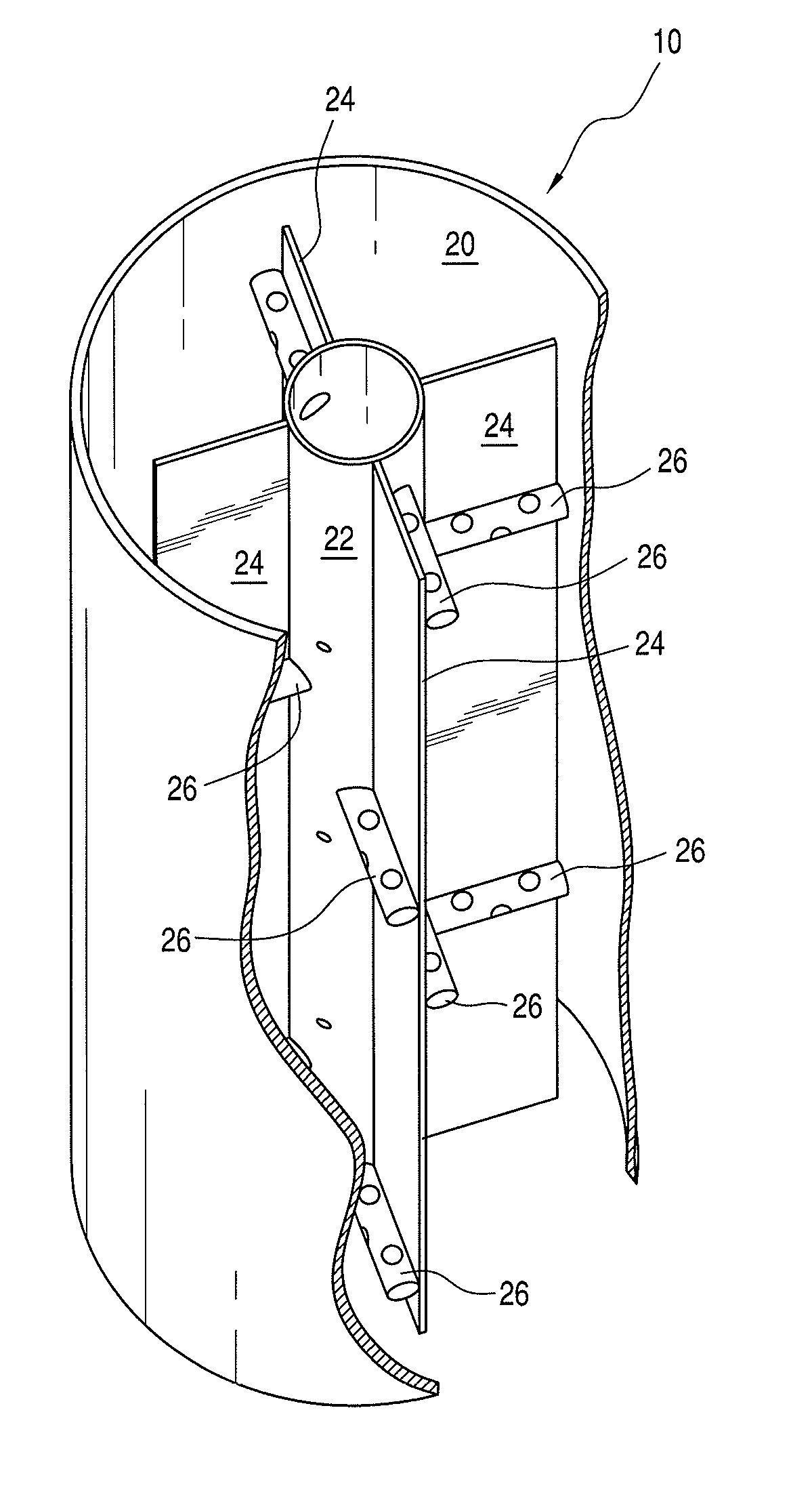
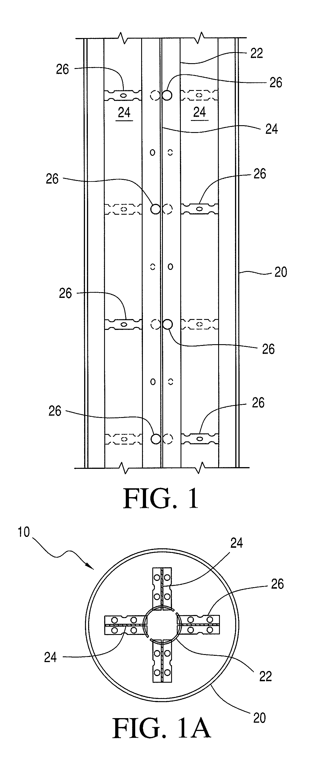
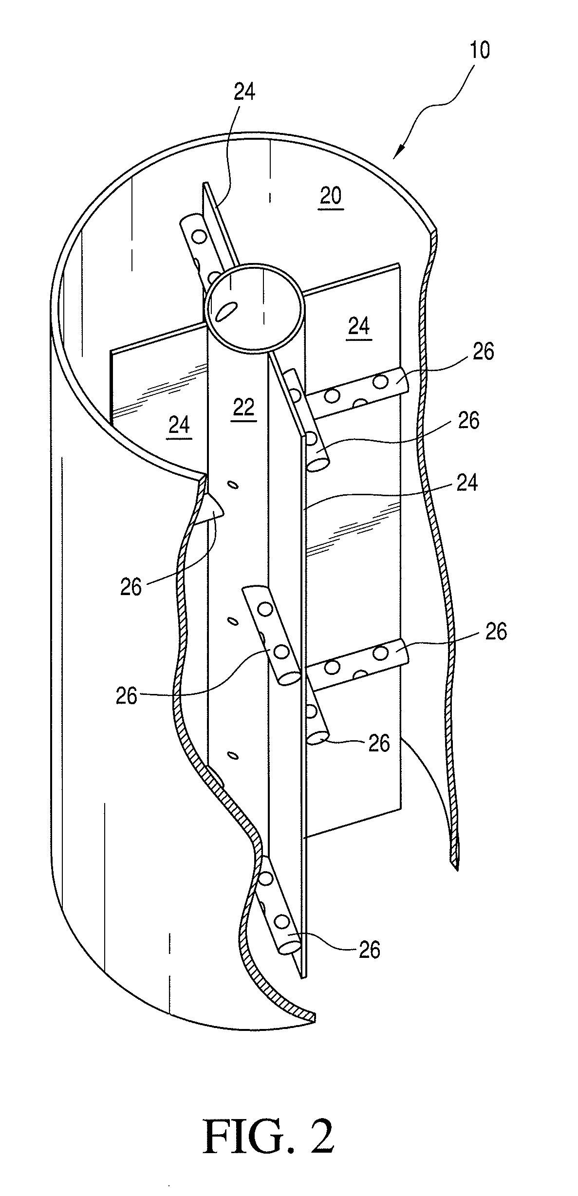
[0021]In a preferred embodiment of the invention, as shown in FIGS. 1, 1A and 2 a centrally located perforated inner vertical tubular member 22 provides reinforcement for the column 10. Rebars and steel plates 24 can also be added for further reinforcement. The perforation of the pipes including the horizontal pipes 26 and the centrally disposed vertical tubular member 22 are all closed with a plurality of water resistant polymer caps for preventing the escape of water or mortar through the openings when the cement is in the plastic state. Further, the plastic caps are melted during a fire thus providing passage for the escape of gases through the pipes and up the inner vertical tubular member 22.

[0022]It should be recognized that the main source of casualties during fires is the inhalation of noxious gases and smoke which are reduced by the novel system disclosed herein. Such systems can channel the gases upwardly through the tubular member 22 from the concrete filled steel tubular...


PUM


Abstract

A concrete filled tubular steel column includes a longitudinally extending vertical tubular steel shell and an inner tubular steel member disposed at the center of the steel shell. A plurality of spaced vertical steel plates extend from the inner members toward but not abutting the steel shell. In addition a plurality of horizontally disposed perforated pipes extend outwardly from the inner member and have a plurality of meltable polymer plugs or caps to prevent plastic cement from flowing into or closing the openings. In the event of fire the plastic or polymer plugs or caps melt and allow gases and smoke to flow into the pipes and up through the inner member and out therefrom at the top of the column.

Description

FIELD OF THE INVENTION[0001]This invention relates to concrete-filled steel tubular columns for high load carrying capacity and more particularly to concrete-filled steel tubular columns which are resistant to fire.BACKGROUND FOR THE INVENTION[0002]Concrete-filled steel tubular columns are today a preferred choice of designers for high load carrying capacity per unit area of cross section of columns. Such columns provide faster construction and no requirement for framework. Patents are available giving descriptions of the methods of construction of such columns and cantilevers. However, the problem associated with this type of construction is in the escape of gases during exposure to relatively intense fires especially when the columns are massive.[0003]This problem is exacerbated with the use of high strength concrete because of the reduced porosity thus providing fewer escape routes for gases during fire exposure. The mixing of polypropelene fibers in the concrete of such members ...

Claims


Application Information

Patent Timeline
Patent Type & Authority Patents(United States)
IPC IPC(8): E04C5/08
CPCE04C3/34
Inventor ABBAS, HUSAINAL-SALLOUM, YOUSEF A.ALSAYED, SALEH H.ALHADDAD, MOHAMMED S.
Owner KING SAUD UNIVERSITY
Why Eureka
Try Eureka