Composite wave gear drive

a gear drive and composite wave technology, applied in the direction of toothed gearings, belts/chains/gearrings, toothed gearings, etc., can solve the problems of low-reduction-ratio gear drives that are available, and achieve the effect of low reduction ratio

Active Publication Date: 2013-07-16
HARMONIC DRIVE SYST IND CO LTD
View PDF19 Cites 21 Cited by
  • Summary
  • Abstract
  • Description
  • Claims
  • Application Information

AI Technical Summary

Benefits of technology

[0011]The composite wave gear drive of the present invention has a composite structure wherein the flexspline is a shared component of unitary construction, while each of the circular spline and wave generator is disposed respectively in pairs. The first wave generator is a rotational input component, and the second wave generator is configured as a reduced-speed rotational output component, whereby it is possible to obtain a backlash-free gear drive having a low reduction ratio. When the second circular spline is used as the reduced-speed rotational output component, it is possible to obtain a backlash-free gear drive having a high reduction ratio, as with an ordinary wave gear drive.

Problems solved by technology

Backlash can occur in low-reduction-ratio gear drives that are available at present, none of which are free of backlash like wave gear drives are.
Backlash-free wave gear drives typically have high reduction ratios; i.e., 1 / 50 or higher The operating principle dictates that these wave gear drives are not suitable for use as low-reduction-ratio gear drives that have a reduction ratio of approximately 1 / 10.

Method used


Image

  • Composite wave gear drive
  • Composite wave gear drive

Examples


Embodiment Construction

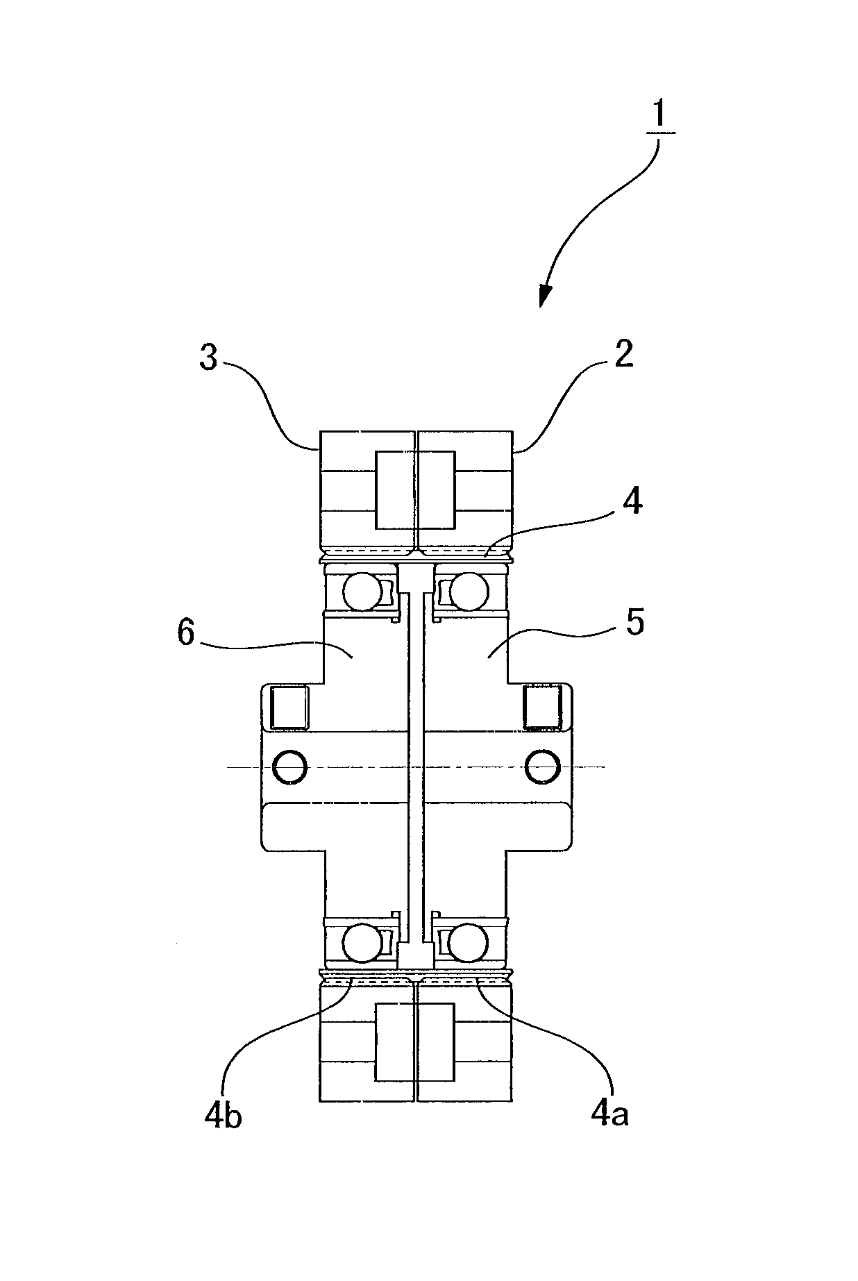
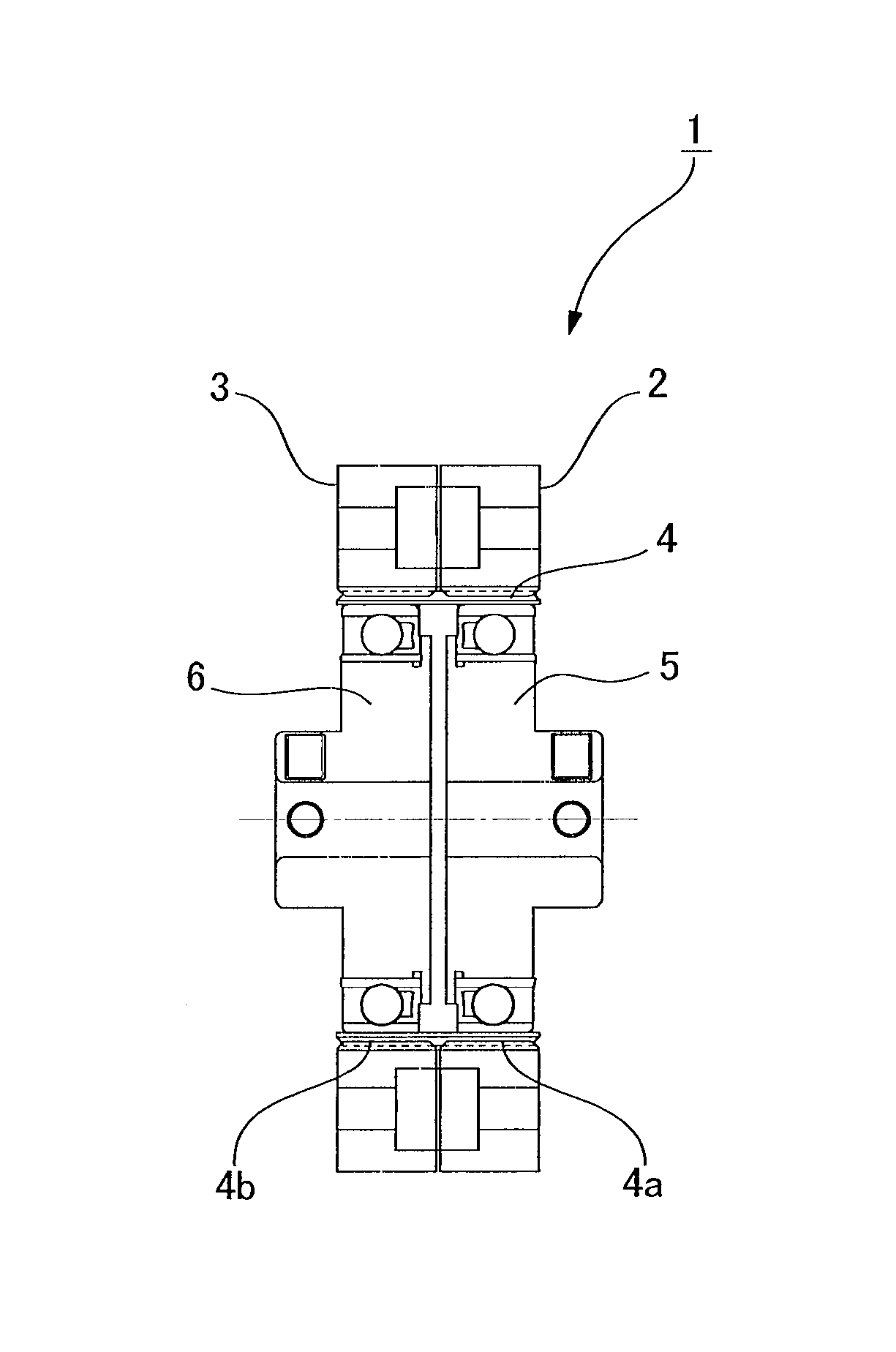
[0013]An embodiment of a composite wave gear drive to which the present invention is applied is described below with reference to the accompanying drawing.

[0014]FIG. 1 is a schematic cross-sectional view of the composite wave gear drive according to the present embodiment. A composite wave gear drive 1 comprises an annular first circular spline 2 and an annular second circular spline 3, which are coaxially disposed in parallel. A cylindrical flexspline 4 capable of coaxially meshing with both the first and second circular splines 2, 3 is disposed on the inner side of the circular splines. A width of the flexspline 4 in the axial direction spans the first and second circular splines 2, 3.

[0015]A first wave generator 5 and a second wave generator 6 having an elliptical outline are fitted on the inner side of the flexspline 4 in a state of being coaxially disposed in parallel The first wave generator 5 is in a position facing the first circular spline 2, and bends a first flexspline po...


PUM


Abstract

In a composite wave gear drive, a flexspline (having a number of teeth Nf) is disposed on the inner side of first and second circular splines (numbers of teeth Nc1 and Nc2, respectively). One side of the flexspline is bent into an elliptical shape by a first wave generator, the other side of the flexspline is bent into an elliptical shape by a second wave generator, and the flexspline meshes with the first and second circular splines. The first wave generator is a rotational input component, the second wave generator is a reduced-speed rotational output component, and the first and second circular splines are kept from rotating. The number of teeth is set such that Nc2=Nc1+2 and Nc1=Nf+2. A backlash-free gear drive having a low reduction ratio can be obtained.

Description

TECHNICAL FIELD[0001]The present invention relates to a composite wave gear drive capable of achieving a low reduction ratio.BACKGROUND ART[0002]Backlash can occur in low-reduction-ratio gear drives that are available at present, none of which are free of backlash like wave gear drives are. Backlash-free wave gear drives typically have high reduction ratios; i.e., 1 / 50 or higher The operating principle dictates that these wave gear drives are not suitable for use as low-reduction-ratio gear drives that have a reduction ratio of approximately 1 / 10. Cup, silk-hat, and flat wave gear devices are disclosed in Patent Documents 1, 2.[0003][Patent Document 1] Japanese Patent No. 3942249[0004][Patent Document 2] Japanese Patent No. 2796109SUMMARY OF THE INVENTION[0005]With the foregoing issues in view, it is an object of the present invention to provide a composite wave gear drive that can be used as a backlash-free gear drive having a low reduction ratio.[0006]In order to solve the aboveme...

Claims


Application Information

Patent Timeline
Patent Type & Authority Patents(United States)
IPC IPC(8): F16H33/00
CPCF16H49/001Y10T74/19F16H1/28F16H1/32
Inventor KANAI, SATORU
Owner HARMONIC DRIVE SYST IND CO LTD
Why Eureka
Try Eureka