Electric brake

A brake, electric technology, applied in the direction of brake type, brake actuator, engine, etc., to achieve the effect of low reduction ratio, reduced position requirements and cost, simple and reliable force introduction

Inactive Publication Date: 2013-05-15
HANNING ELECTRO WERKE GMBH & CO KG
View PDF9 Cites 5 Cited by
  • Summary
  • Abstract
  • Description
  • Claims
  • Application Information

AI Technical Summary

Problems solved by technology

But the disadvantage of this known brake is that the force transmission flow extends directly from the threaded roller via the two axial bearings to the brake operating element;

Method used


Image

  • Electric brake
  • Electric brake
  • Electric brake

Examples


Embodiment Construction

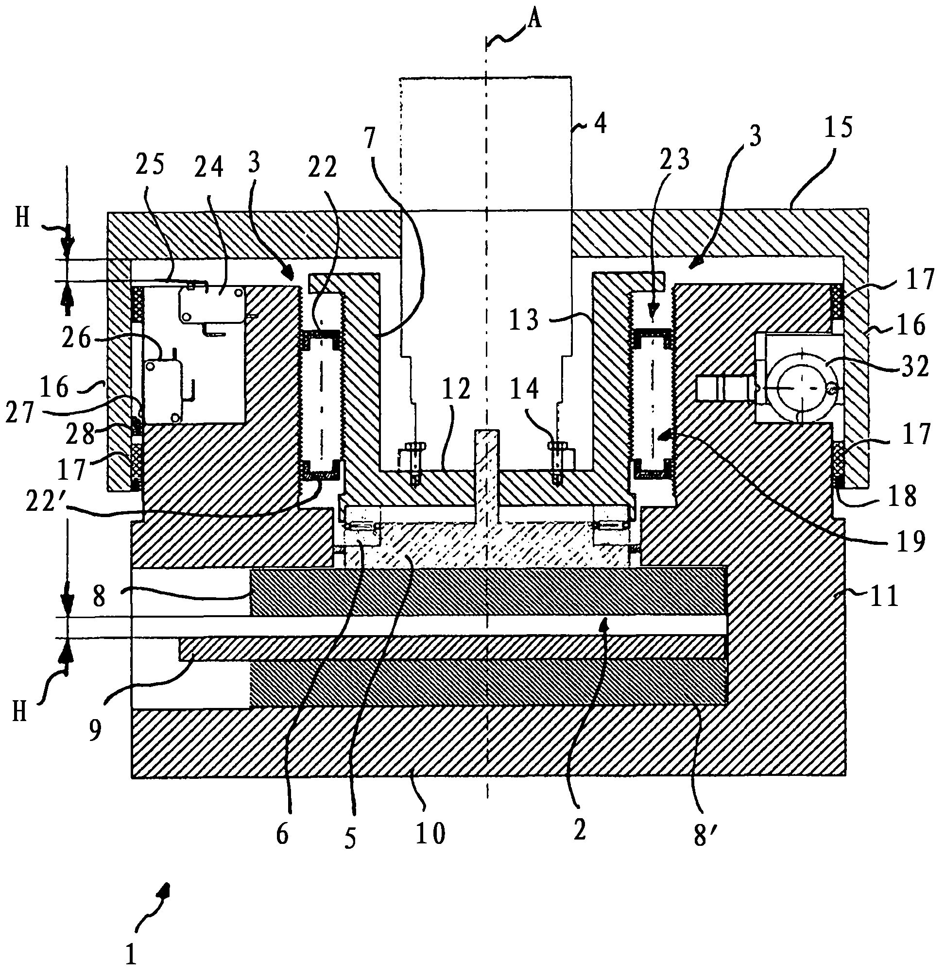
[0023] The brake 1 according to the invention can preferably be used in a wind power plant for braking a rotor blade. Alternatively, the brake 1 can also be used in a braking system for a sun-tracking device or in a braking system in the field of mechanical engineering or medical technology.

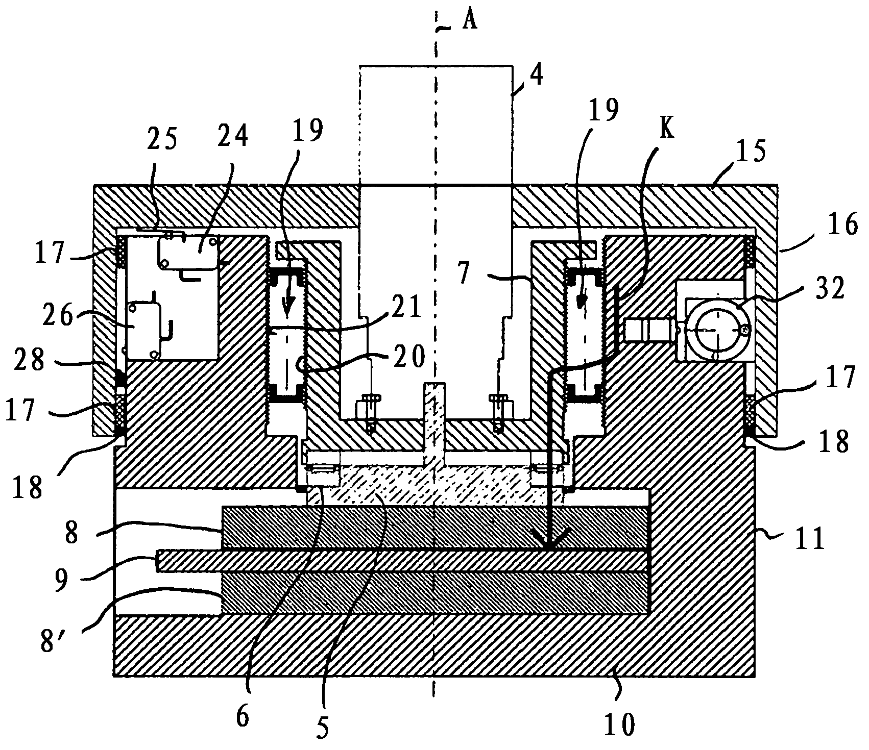
[0024] Brake 1 essentially has a brake actuating element 2 (brake shoe), a planetary roller screw unit 3 coupled to brake actuating element 2 , and an electric drive 4 coupled to planetary roller screw unit 3 .

[0025] The brake actuating element 2 has on the one hand a holding disk 5 which is coupled to a bell-shaped spindle element 7 via an axial bearing 6 designed as a needle bearing. On the other hand, the holding disc 5 of the brake operating element 2 has a brake lining 8 on the side facing away from the spindle element 7 , which brake lining 8 when the brake 1 is actuated, that is to say in the axial direction of the brake operating element 2 . When exercising by figure 1 The n...


PUM


Abstract

The invention relates to a brake, comprising at least one brake actuating element, which is operatively connected to a planetary-roller threaded unit and to an electrical drive in order to move the brake actuating element between a braking position and an axially offset non-braking position of the brake actuating element, wherein the planetary-roller threaded unit has a plurality of threaded roller elements distributed in the circumferential direction, the threaded roller elements being in threaded engagement with a spindle element connected in a rotationally fixed manner to the electrical drive and with a stationary housing, and wherein the threaded roller elements are rotatably arranged about the axes thereof, which are each arranged parallel to an axis of the spindle element, and about the axis of the spindle element, wherein the brake actuating element is coupled only to the spindle element.

Description

technical field [0001] The invention relates to a brake for, for example, a wind power plant, having at least one brake actuating element, which is operatively connected to a planetary roller screw unit and an electric drive, so that during braking actuation Adjusting the brake actuating element between the braking position of the element and the axially offset non-braking position, wherein the planetary roller screw unit has a plurality of threaded rollers arranged distributed in the circumferential direction, the threaded rollers On the one hand, it is in threaded engagement with the threaded screw element, which is connected to the electric drive in a non-rotatable manner, and on the other hand, it is in threaded engagement with the fixedly arranged housing, and the threaded roller around its own axis and around the threaded screw The axes of the elements are rotatably arranged, the axes of the threaded rollers are respectively parallel to the axes of the screw elements. ...

Claims


Application Information

Patent Timeline
Patent Type & Authority Applications(China)
IPC IPC(8): F16D65/56F03D11/00F16D65/18
CPCF16D2125/40F16D65/18F05B2260/903F05B2260/902F16D2066/003Y02E10/722Y02E10/72F03D11/00F16D2121/24F16D2125/48F16D65/56F16D2125/50F16H25/2252F03D80/00
Inventor M·里奇
Owner HANNING ELECTRO WERKE GMBH & CO KG
Why Eureka
Try Eureka