Marine propulsion system

a propulsion system and marine technology, applied in marine propulsion, vessel parts, vessel construction, etc., can solve the problems of difficult to achieve a larger maximum speed, difficult to improve acceleration performance in a low speed position, and difficult for users to achieve both acceleration performance and maximum speed approaching the levels that they/they desir

Inactive Publication Date: 2011-03-22
YAMAHA MOTOR CO LTD
View PDF7 Cites 9 Cited by
  • Summary
  • Abstract
  • Description
  • Claims
  • Application Information

AI Technical Summary

Benefits of technology

[0006]In order to overcome the problems described above, preferred embodiments of the present invention provide a marine propulsion system in which both an acceleration performance and a maximum speed can approach levels that a user desires.
[0008]As described above, the marine propulsion system in accordance with the above preferred embodiment includes a transmission mechanism arranged to transmit the driving force generated by the engine to the propeller with the speed shifted to one of the low speed reduction ratio and the high speed reduction ratio. The transmission mechanism is arranged such that the driving force generated by the engine can be transmitted to the propeller with the speed shifted to the low speed reduction ratio. Accordingly, an acceleration performance in the low speed position can be improved. Further, the transmission mechanism is constructed such that the driving force generated by the engine can be transmitted to the propeller with the speed shifted to the high speed reduction ratio. This allows a larger maximum speed to be obtained. As a result, both the acceleration performance and the maximum speed can approach levels that the user desires. The user operates the operation portion and thereby can arbitrarily shift the speed reduction ratio of the transmission mechanism to the low speed reduction ratio in the reverse travel.

Problems solved by technology

However, the marine propulsion unit disclosed in JP-A-Hei 9-263294 has a problem in which it is difficult to improve acceleration performance in a low speed position when the speed reduction ratio of the power transmission mechanism is set to achieve a larger maximum speed.
Conversely, there is a problem that it is difficult to achieve a larger maximum speed when the reduction ratio of the power transmission mechanism is set to improve the acceleration performance in the low speed position.
In other words, the marine propulsion unit disclosed in JP-A-Hei 9-263294 has a problem in which it is difficult for the user to achieve both an acceleration performance and a maximum speed approaching the levels that he / she desires.

Method used


Image

  • Marine propulsion system
  • Marine propulsion system
  • Marine propulsion system

Examples


Embodiment Construction

[0023]Preferred embodiments of the present invention will be described hereinafter with reference to the drawings.

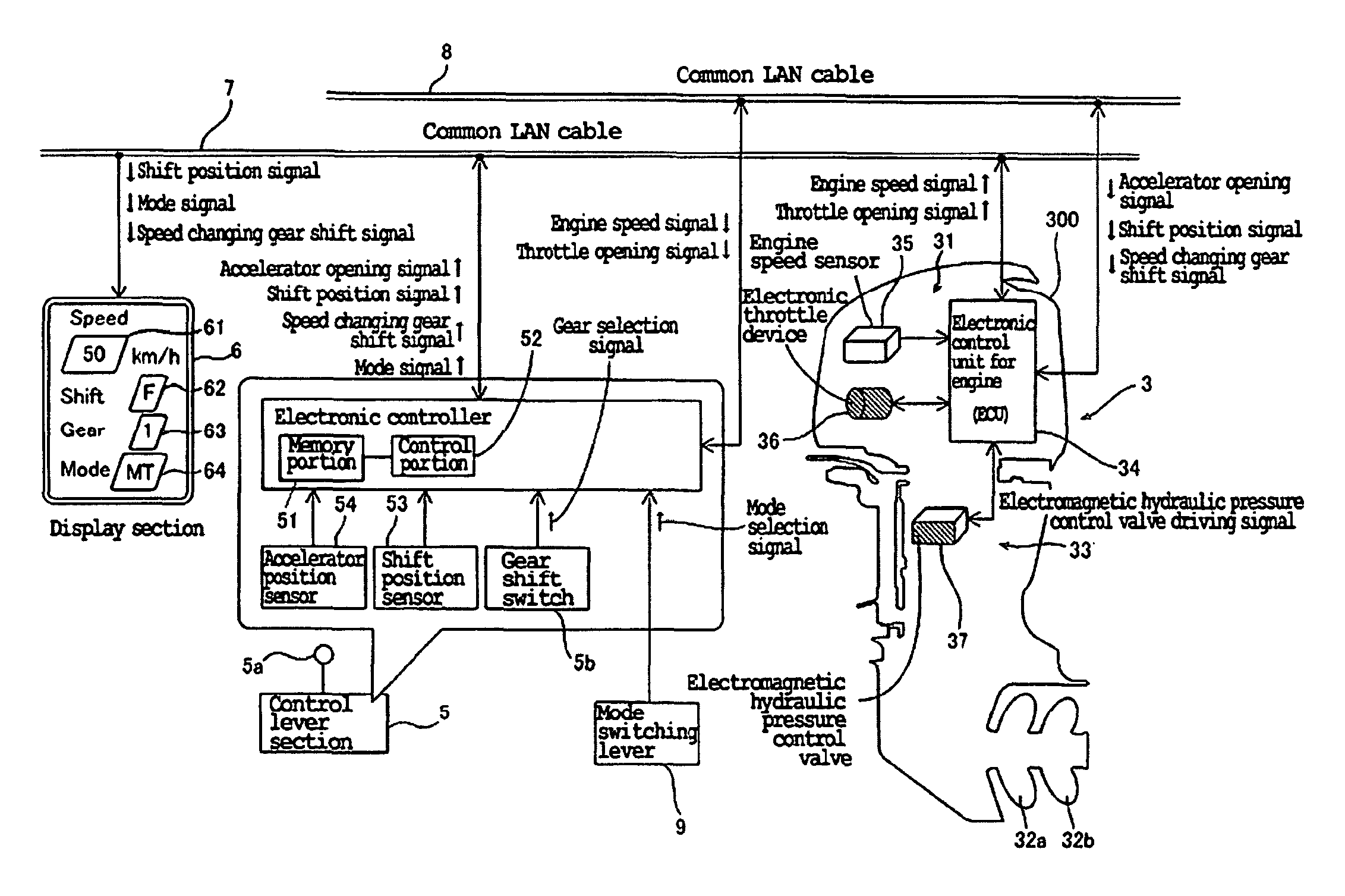
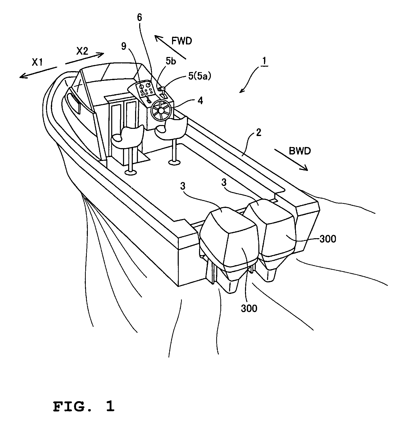
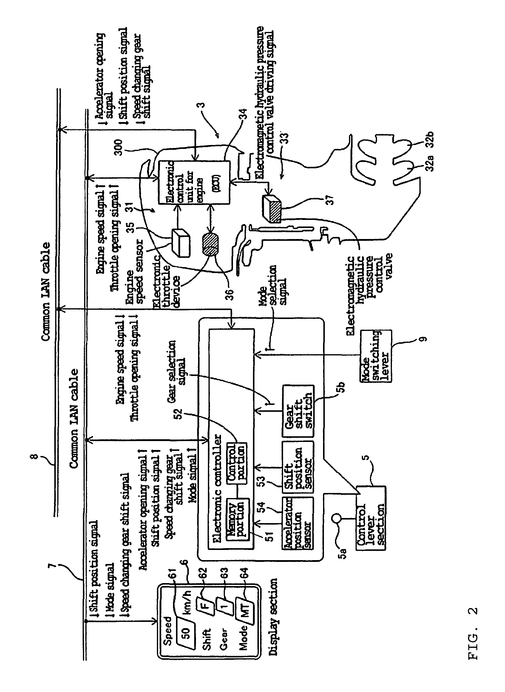
[0024]FIG. 1 is a perspective view showing a boat in which a marine propulsion system in accordance with a preferred embodiment of the present invention is installed. FIG. 2 is a block diagram showing a construction of the marine propulsion system in accordance with a preferred embodiment of the present invention. FIGS. 3 through 9 are drawings specifically illustrating the construction of the marine propulsion system in accordance with the preferred embodiment shown in FIG. 1. In the figures, arrow FWD indicates the forward travel direction of the boat, and arrow BWD indicates the reverse travel direction of the boat. First, the construction of a boat 1 and the marine propulsion system installed in the boat 1 in accordance with a preferred embodiment of the present invention will be described with reference to FIGS. 1 through 9.

[0025]As shown in FIG. 1, the boat 1 in ac...


PUM


Abstract

A marine propulsion system includes an engine, propellers rotated by the engine, a transmission mechanism arranged to transmit a driving force of the engine to the propellers with a speed thereof shifted to at least a low speed reduction ratio or a high speed reduction ratio in forward travel and reverse travel, and a gear shift switch operable by a user to shift speed reduction ratios of the transmission mechanism to the low speed reduction ratio in at least the reverse travel. This arrangement provides a marine propulsion system in which both of acceleration performance and a maximum speed can approach levels that a user desires.

Description

BACKGROUND OF THE INVENTION[0001]1. Field of the Invention[0002]The present invention relates to a marine propulsion system. More specifically, the present invention relates to a marine propulsion system including an engine.[0003]2. Description of the Related Art[0004]Conventionally, marine propulsion units (marine propulsion systems) including an engine are known in the art (for example, see JP-A-Hei 9-263294). JP-A-Hei 9-263294 discloses a marine propulsion unit including an engine and a power transmission mechanism transmitting a driving force of the engine to a propeller in a certain fixed reduction ratio. The marine propulsion unit is constructed such that the driving force of the engine is directly transmitted to the propeller via the power transmission mechanism and the rotational speed of the propeller increases proportionally with an increase in the engine speed.[0005]However, the marine propulsion unit disclosed in JP-A-Hei 9-263294 has a problem in which it is difficult t...

Claims


Application Information

Patent Timeline
Patent Type & Authority Patents(United States)
IPC IPC(8): B60W10/04B63H21/21
CPCB63H21/213B63H23/08B63H23/30
Inventor SUZUKI, TAKAYOSHINAKAMURA, DAISUKE
Owner YAMAHA MOTOR CO LTD
Why Eureka
Try Eureka