
Spectral-beam combining for high-power fiber-ring-laser systems

a fiber-ring laser and fiber-laser technology, applied in the field of ring lasers and spectral beam combining, can solve the problems of power limitations or even the destruction of a high-power fiber-laser system, the output power of fiber lasers is not expected to scale much beyond 10 kw, and the power scaling of individual fiber laser channels is difficult, so as to reduce the energy absorption of optical elements, reduce or prevent the chromatic dispersion of output beams, and small numerical apertur

Active Publication Date: 2013-09-03
LOCKHEED MARTIN CORP
View PDF148 Cites 67 Cited by
  • Summary
  • Abstract
  • Description
  • Claims
  • Application Information

AI Technical Summary

Benefits of technology

The present invention is an improved laser system that combines the output of multiple ring lasers using efficient optical components. The use of high-efficiency gratings and focussing reflectors reduces energy absorption, while chromatic-dispersion-compensation gratings prevent beam distortion. Optical gain fibers are used in the ring lasers, which can also be doped with rare-earths. The system includes a highly reflective output reflector and a low-transmissive backward-wave reflector to ensure one-directional lasing around the ring. The technical effects of this invention are a more powerful and efficient laser system with improved beam quality and stability.

Problems solved by technology

The fiber lasers have demonstrated up to a few thousand Watts (kW) with broad linewidths but the fiber laser output power is not expected to scale much beyond 10 kW due to thermal loading and optical nonlinear effects.
Both approaches require narrow linewidths on the order of a few GHz, which makes the power scaling of individual fiber laser channels challenging, primarily due to limitation posed by stimulated Brillouin scattering (SBS) in fiber.
(Stimulated Brillouin scattering (SBS) is a well-known phenomenon that can lead to power limitations or even the destruction of a high-power fiber-laser system due to sporadic or unstable feedback, self-lasing, pulse compression and / or signal amplification.)
Coherent-beam combination produces spectrally bright beams but suffers from multi-lobed far-field transverse profiles with off-axis sidelobes.
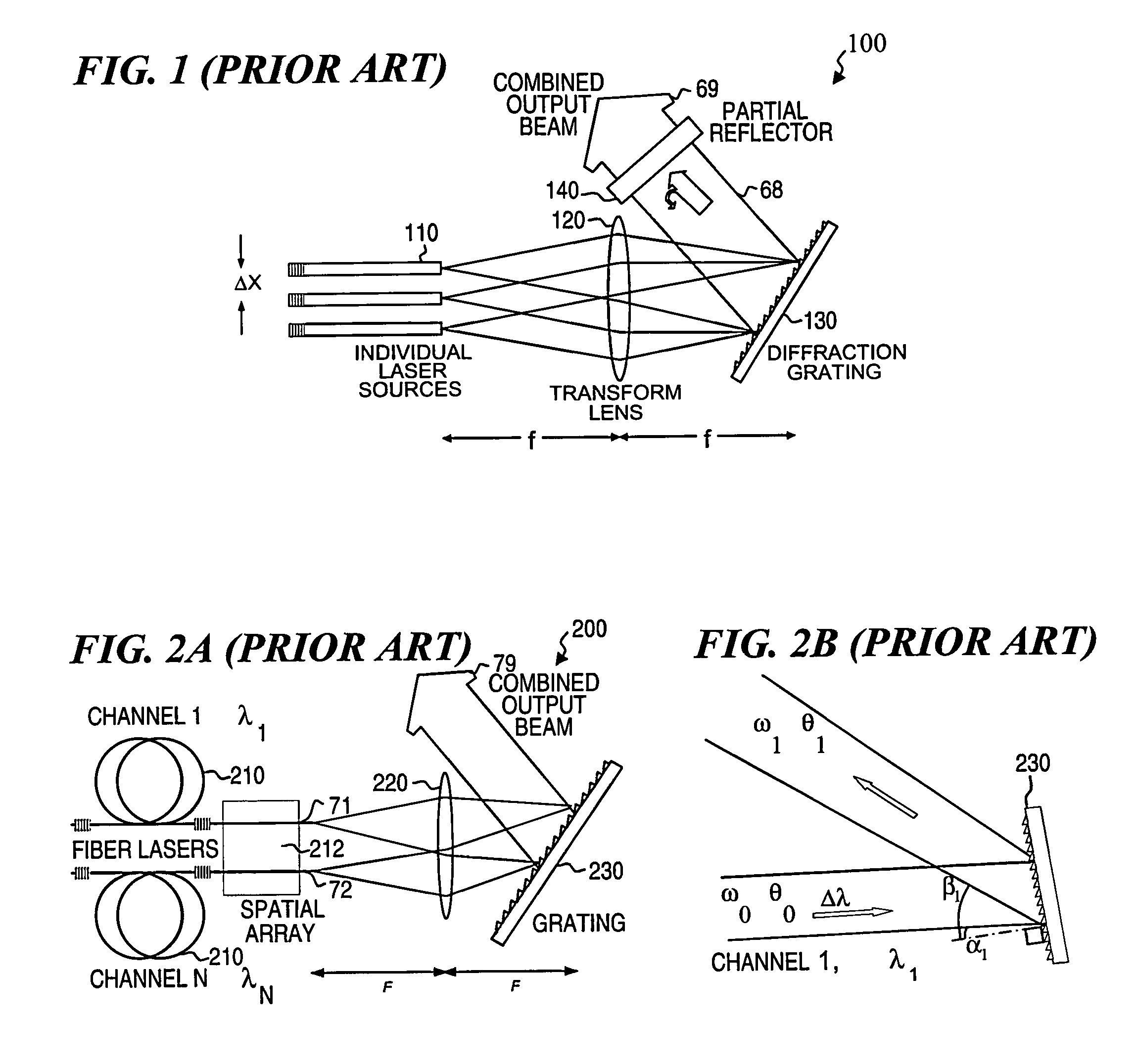
System 100 has the disadvantage that the highest-power beam (output beam 69) passes through the output reflector 140, which can result in undesirable energy absorption in the output reflector 140.
System 100 also has the disadvantage that output beam 69 continues to chromatically disperse after it diffracts from uncompensated grating 130 and passes through the output reflector 140, which can result in undesirable beam quality.
One of the challenges in early applications of the optical design of FIG. 1 to fiber lasers was the operation of the fiber lasers as linear oscillators with the required narrow linewidth.
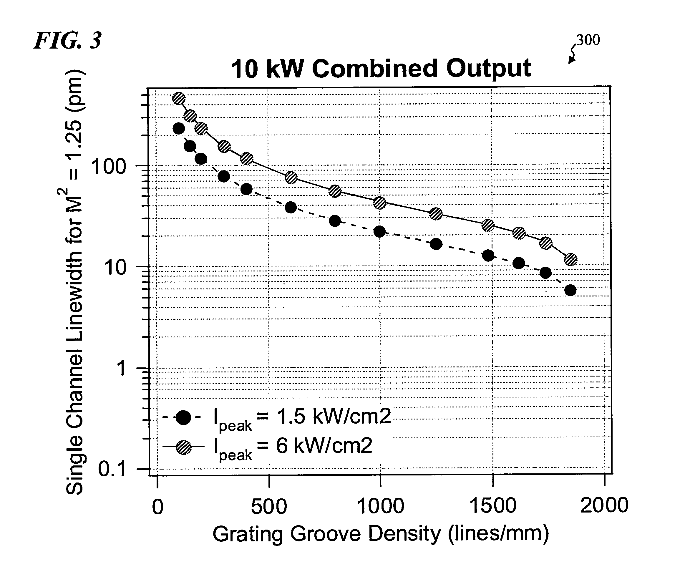
From the above equations, one sees that for given values of Δλ and g, increasing ω0 decreases Ipeak (i.e., the thermal load on the grating) but simultaneously reduces the combined beam quality.
The power that can be generated from fiber lasers and fiber-laser amplifiers can often be limited by nonlinear optical effects in the gain and / or delivery fibers used in the system.
Using relatively large-core, low-NA fibers with mode-filtering techniques has been demonstrated to achieve good beam quality, but there are practical disadvantages to the use of such fibers.
Fibers with very low values of NA exhibit large bending losses, even for relatively large-radius bends.
With fibers having the lowest NA, the fiber must be kept quite straight, otherwise the optical amplifier and / or laser has very low efficiency as the bending loss becomes too high.
Since a typical laser oscillator or amplifier might require on the order of a meter or more of gain fiber, the inability to coil the fiber has precluded compact packaging of the fiber-laser system.

Method used


Image

  • Spectral-beam combining for high-power fiber-ring-laser systems
  • Spectral-beam combining for high-power fiber-ring-laser systems
  • Spectral-beam combining for high-power fiber-ring-laser systems

Examples


Embodiment Construction

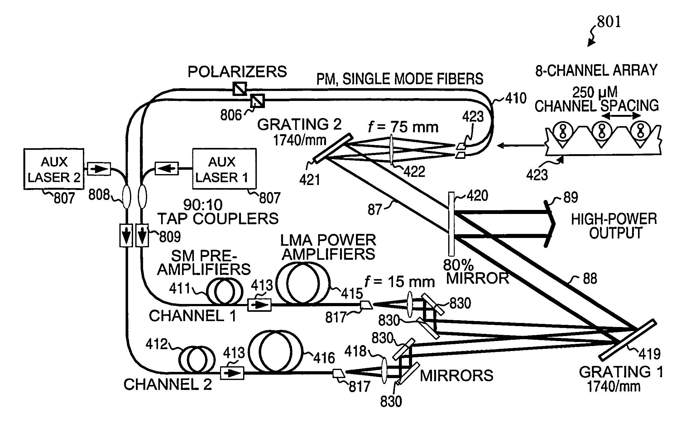
[0061]In the following detailed description of the preferred embodiments, reference is made to the accompanying drawings that form a part hereof, and in which are shown by way of illustration specific embodiments in which the invention may be practiced. It is understood that other embodiments may be utilized and structural changes may be made without departing from the scope of the present invention.

[0062]The leading digit(s) of reference numbers appearing in the Figures generally corresponds to the Figure number in which that component is first introduced, such that the same reference number is used throughout to refer to an identical component which appears in multiple Figures. Signals and connections may be referred to by the same reference number or label, and the actual meaning will be clear from its use in the context of the description.

[0063]One of the challenges in a multi-channel SBC system is to have the wavelength of individual channels tuned to the correct wavelength for...


PUM


Abstract

A ring-laser system that includes a plurality of ring-laser gain elements and a spectral-beam-combining output stage configured to combine a plurality of beams coming from the gain elements into an output beam and that includes chromatic-dispersion compensation. In some embodiments, the output stage includes a plurality of highly reflective dielectric-coated focussing elements. In some embodiments, the output stage includes a plurality of high-efficiency dielectric-coated grating elements. In some embodiments, the output stage includes a mostly reflective but partially transmissive output mirror and a highly reflective beam-reversing mirror configured to reflect a majority of a backward-traveling signal beam such that it becomes forward traveling. In some embodiments, each gain element further includes a photonic-crystal-rod power amplifier. Some embodiments have an amplitude modulator configured to pulse the plurality of beams, and a timing controller configured to synchronize the pulses of the plurality of beams. Some embodiments further include a non-linear wavelength-conversion device.

Description

RELATED APPLICATIONS[0001]This application claims benefit under 35 U.S.C. §119(e) of U.S. Provisional Patent Application No. 61 / 029,304, filed Feb. 15, 2008, which is incorporated herein by reference in its entirety.[0002]The application is related to U.S. Pat. No. 7,199,924, filed Jan. 26, 2006 and issued Apr. 3, 2007, titled APPARATUS AND METHOD FOR SPECTRAL-BEAM COMBINING OF HIGH-POWER FIBER LASERS, U.S. Pat. No. 7,391,561, filed May 26, 2006 and issued Jun. 24, 2008, titled FIBER- OR ROD-BASED OPTICAL SOURCE FEATURING A LARGE-CORE, RARE-EARTH-DOPED PHOTONIC-CRYSTAL DEVICE FOR GENERATION OF HIGH-POWER PULSED RADIATION AND METHOD, U.S. patent application Ser. No. 12 / 053,551 filed Mar. 21, 2008 and titled HIGH-POWER, PULSED RING FIBER OSCILLATOR (which issued as U.S. Pat. No. 7,876,803 on Jan. 25, 2011), U.S. patent application Ser. No. 12 / 165,651 filed Jun. 30, 2008 and titled METHOD AND APPARATUS FOR SPECTRAL-BEAM COMBINING OF FANNED-IN LASER BEAMS WITH CHROMATIC-DISPERSION COMPE...

Claims


Application Information

Patent Timeline
Patent Type & Authority Patents(United States)
IPC IPC(8): G02B27/64
CPCH01S3/06791H01S3/2391G02B27/0905G02B27/1086H01S3/06712H01S3/06741H01S3/0812H01S3/117H01S3/1618
Inventor HONEA, ERIC C.LOFTUS, THOMAS H.LEMAIRE, CHARLES A.
Owner LOCKHEED MARTIN CORP
Learn More