Spread spectrum radar apparatus

a radar and spread spectrum technology, applied in the direction of reradiation, measurement devices, instruments, etc., can solve the problems of increasing the dynamic range of the receiver, difficult to lower the price of the apparatus, and affecting the accuracy of the signal, so as to achieve the effect of low noise to peak output ratio, wide detection range, and high performan

Inactive Publication Date: 2010-01-05
PANASONIC CORP
View PDF26 Cites 62 Cited by
  • Summary
  • Abstract
  • Description
  • Claims
  • Application Information

AI Technical Summary

Benefits of technology

[0019]According to the present invention, it is possible to provide a spread spectrum radar apparatus which is configured of a circuit in which a local oscillator which is common in the reception and transmission sides is used but a direct current amplifier is not required, and which is inexpensive, has a wide detection range, and provides high performance.
[0020]Furthermore, in the conventional technology, an exclusive OR is calculated between the data supplied from a data source (bits) and the transmission PN code in the transmission side. Then, since the code obtained from the exclusive OR is modulated using an oscillator signal supplied from the local oscillator, large numbers of spectrum caused by the bits appear in each of the frequencies of spectrum for the signal obtained by the modulation. With this, the number of spectrums becomes large, inter-modulation occurs between those spectrums due to the non-linearity caused by a balanced modulator, an amplifier, and the like. With this, the despread processing in the receiving side deteriorates a correlation characteristic with the delaying PN code, and a ratio of noise to peak in output of the reception signal becomes lower. In other words, such case is equivalent to a case where an object having high reflectivity properties is masked by an object having low reflectivity properties. Thus, the object detection capability of the spread spectrum radar apparatus decreases.
[0021]For solving this, the spread spectrum radar apparatus according to the present invention uses a local oscillator, instead of the data source. Since the number of spectrums is less in a signal emitted from a transmission unit as a detection radio wave, such spectrums are less subject to the inter-modulation. Thus, it is possible to suppress the occurrence of spurious signals that impedes a receiving operation.

Problems solved by technology

However, according to the aforementioned conventional technology, a frequency stabilizer using a phase-locked loop is necessary in each reception side and transmission side of the spread spectrum radar apparatus using a heterodyne method, and thus, there is a problem that it is difficult to lower the price of the apparatus.
However, there is a characteristic that a problem to be described hereinafter which is unique to the homodyne method does not occur in a spread spectrum radar apparatus using the heterodyne method.
On the other hand, the spread spectrum radar apparatus using the homodyne method has problems, such as characteristic variations in semiconductor devices, direct current offsets caused by the variation in the ambient temperature, and thus, it is necessary to install a direct current amplifier.
Since the detection range of the radar apparatus is set wide, it becomes a substantial obstacle when the dynamic range of the receiver is increased.

Method used


Image

  • Spread spectrum radar apparatus
  • Spread spectrum radar apparatus
  • Spread spectrum radar apparatus

Examples


first embodiment

[0084]Hereinafter, the first embodiment according to the present invention is described with reference to the diagrams.

[0085]The spread spectrum radar apparatus of the present embodiment includes the features (a) to (j) as shown below.

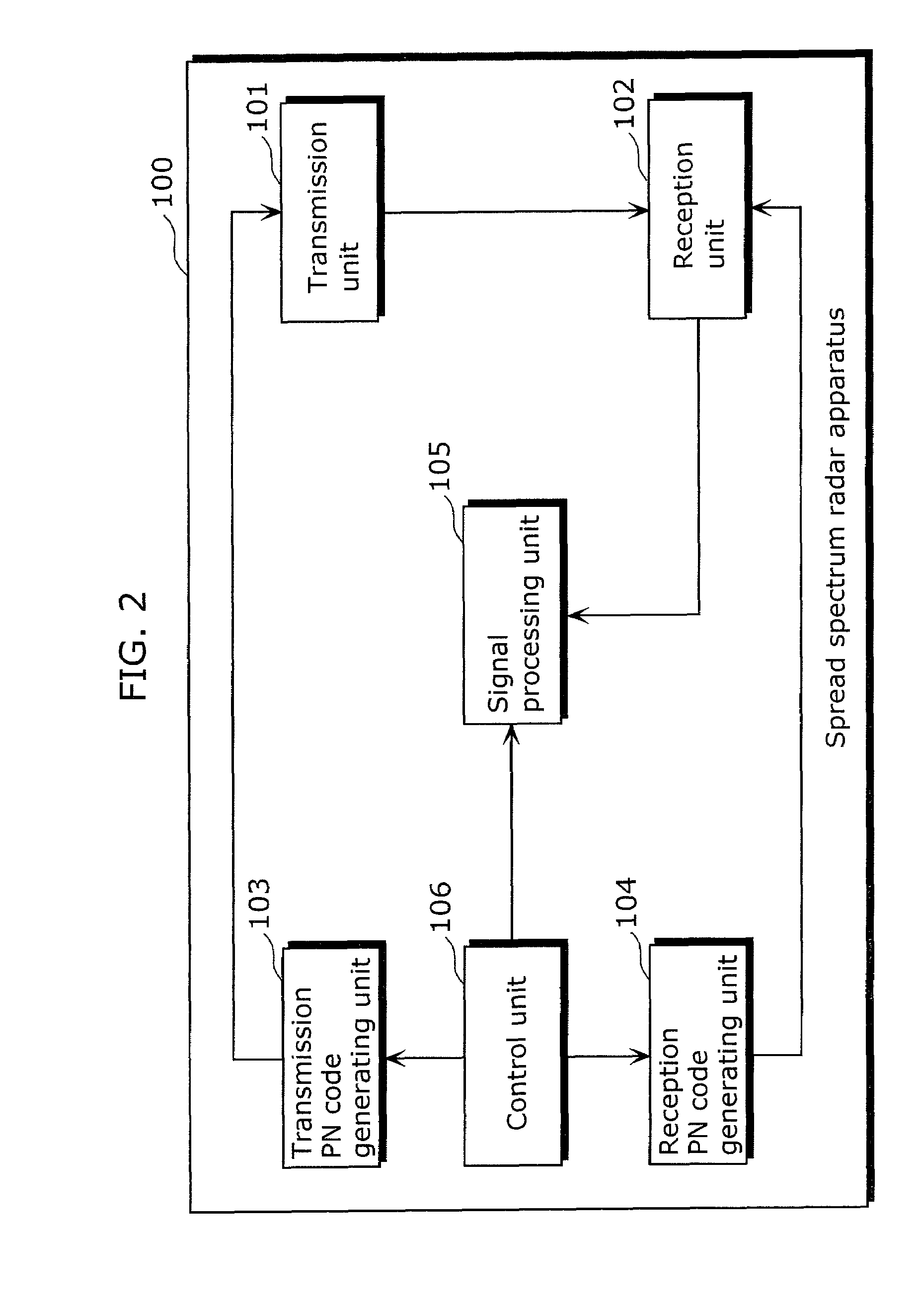
[0086](a) The spread spectrum radar apparatus includes: (a1) a transmission circuit which generates a spread signal that is a spectrum-spread signal, using a first oscillator signal, a second oscillator signal, and a first pseudo-noise code, and which emits the spread signal as a detection radio wave; (a2) a reception circuit which receives, as a reception signal, the detection radio wave reflected from an object, and which generates an intermediate frequency signal by despreading the reception signal based on the first oscillator signal and a second pseudo-noise code obtained by delaying the first pseudo-noise code, and (a3) wherein a frequency of the first pseudo-noise code is larger than a frequency of the second oscillator signal.

[0087](b) The rece...

second embodiment

[0151]Hereinafter, the second embodiment according to the present invention is described with reference to the diagrams.

[0152]The spread spectrum radar apparatus of the present embodiment includes the features (a) and (b) as shown below.

[0153](a) The quadrature demodulator further includes: (a1) a phase shifter which alternately outputs the first oscillator signal and a third oscillator signal in which a shift amount with respect to the first oscillator signal is different by 90 degrees; and (a2) a balanced modulator which alternately generates the in-phase signal and the quadrature signal by mixing the modulation signal and the signal outputted from the phase shifter.

[0154](b) The reception circuit further includes: (b1) a band-pass filter to which the in-phase signal and the quadrature signal are alternately inputted from the quadrature demodulator, and which allows a band from among frequency components of the in-phase signal and the quadrature signal, the band having a frequency...

third embodiment

[0177]Hereinafter, the third embodiment according to the present invention is described with reference to the diagrams.

[0178]The spread spectrum radar apparatus of the present embodiment includes a feature (a) as shown below.

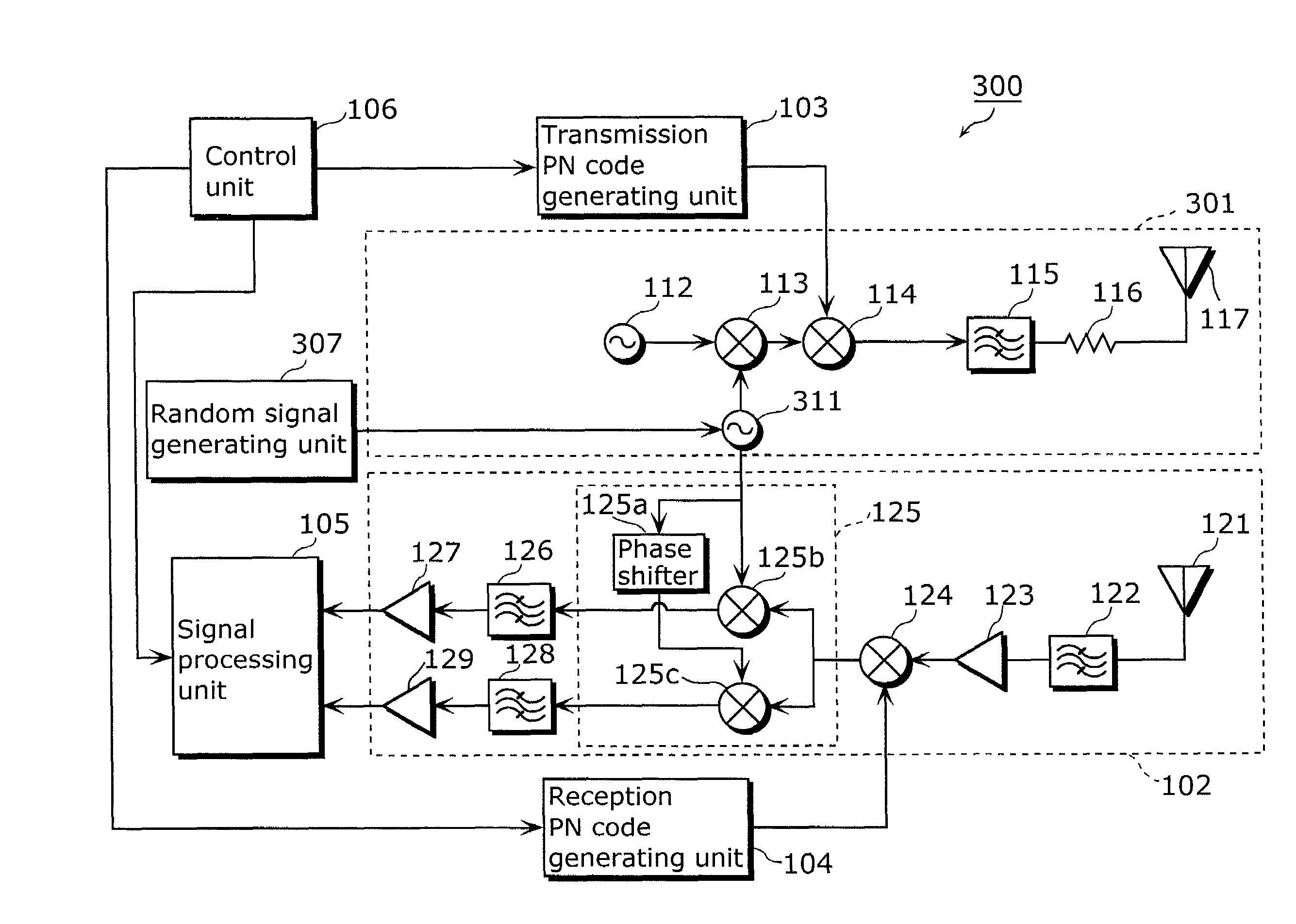
[0179](a) The spread spectrum radar apparatus further includes a random signal generating circuit which generates a random signal that randomly changes a frequency of the first oscillator signal.

[0180]In view of the aforementioned point, the spread spectrum radar apparatus according to the present embodiment is described. Note that the description of the constituent units of the third embodiment which are identical to the constituent units of the first embodiment is omitted using the same unit numbers.

[0181]First, the spread spectrum radar apparatus according to the present embodiment is described.

[0182]As shown in FIG. 7, the spread spectrum radar apparatus 300 differs from the spread spectrum radar apparatus 100 of the first embodiment (for example, refer to F...


PUM


Abstract

A spread spectrum radar apparatus includes: a transmission unit which generates a spread signal that is a spectrum-spread signal, using a first oscillator signal, a second oscillator signal, and a transmission PN code, and which emits the spread signal as a detection radio wave; and a reception unit which receives, as a reception signal, the detection radio wave reflected from an object, and which generates an intermediate frequency signal by despreading the reception signal based on the first oscillator signal and a reception PN code obtained by delaying the transmission PN code.

Description

TECHNICAL FIELD[0001]The present invention relates to a radar apparatus using a spread spectrum method, and particularly to a spread spectrum radar apparatus which is inexpensive, has a wide detection range, and provides high performance.BACKGROUND ART[0002]In recent years, technical development on radar apparatuses installed in vehicles (hereinafter referred to as on-vehicle radar apparatuses) is actively underway. As one of the examples, a radar apparatus using a spread spectrum method (hereinafter referred to as a spread spectrum radar apparatus) and the like has been suggested (for example, refer to Patent Reference 1).[0003]On-vehicle radar apparatuses are used to detect a preceding vehicle, a rear obstacle, and the like, for the purpose of safety improvement such as collision avoidance and enhancement of the driving convenience represented by reverse driving support. When the on-vehicle radar apparatuses are used for such purposes, it is necessary to suppress an effect of an u...

Claims


Application Information

Patent Timeline
Patent Type & Authority Patents(United States)
IPC IPC(8): G01S7/28G01S7/282H04B1/707H04B1/69G01S7/285G01S13/00G01S13/93G01S13/26G01S13/32
CPCG01S7/35G01S13/325
Inventor FUKUDA, TAKESHI
Owner PANASONIC CORP
Why Eureka
Try Eureka