Lever-type connector with collective rubber stopper

a technology of collective rubber stopper and lever-type connector, which is applied in the direction of coupling/support/case, coupling device connection, electrical equipment, etc., can solve the problems of deformation of the outer wall of the frame and adversely affect the waterproof performan

Active Publication Date: 2013-07-16
SUMITOMO WIRING SYST LTD
View PDF15 Cites 5 Cited by
  • Summary
  • Abstract
  • Description
  • Claims
  • Application Information

AI Technical Summary

Benefits of technology

[0013]The peripheral surface of the collective rubber stopper is surrounded with the tubular protection part and thus protected from interference of foreign matter in the state before the sub-connector and the collective rubber stopper are mounted on the concave accommodation portions. This protection of the peripheral surface of the collective rubber stopper from damage prevents deterioration in the sealing performance of the connector. Further, the separated space is utilized effectively for accommodating the tubular protection part. Thus, the tubular protection part will not project significantly outside when the holder is mounted on the frame. Thus, the first housing need not be large.
[0014]Deformation of the outer wall caused by operation of the operation member greatly affects the sides disposed in the direction intersecting the rotating shaft of the operation member. However, the separated space is disposed along the sides intersecting the rotating shaft of the operation member. Thus, it is possible to avoid the influence of the deformation of the outer wall due to the operation of the operation member.
[0016]Wrong coupling prevention parts are formed on the connector unit and the frame to prevent an incorrect combination of a connector unit and a concave accommodation portion.

Problems solved by technology

Thus, there is a fear that the outer wall of the frame will deform.
Such a deformation will generate a gap between inner surfaces of the concave accommodation portions and the outer surface of the collective rubber stopper and could adversely affect the waterproof performance.

Method used


Image

  • Lever-type connector with collective rubber stopper
  • Lever-type connector with collective rubber stopper
  • Lever-type connector with collective rubber stopper

Examples


Embodiment Construction

[0025]A connector in accordance with the invention has first and second housings 10 and 60 and a lever 80, as shown in FIG. 5. The connector has a waterproof function and a means for preventing deterioration of the sealing performance when the lever 80 is pivoted.

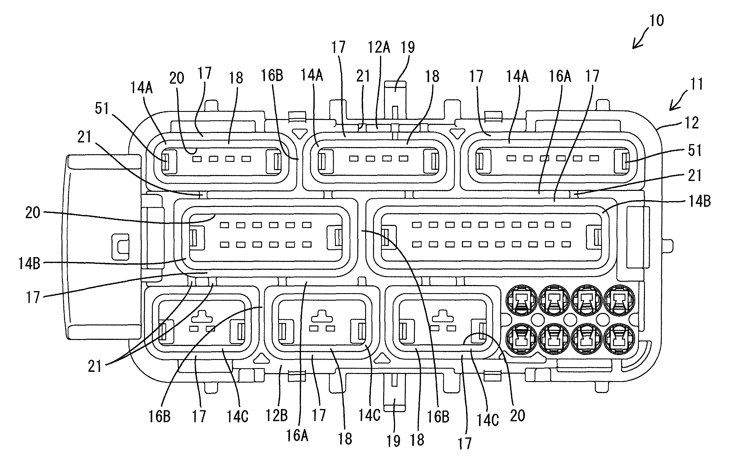
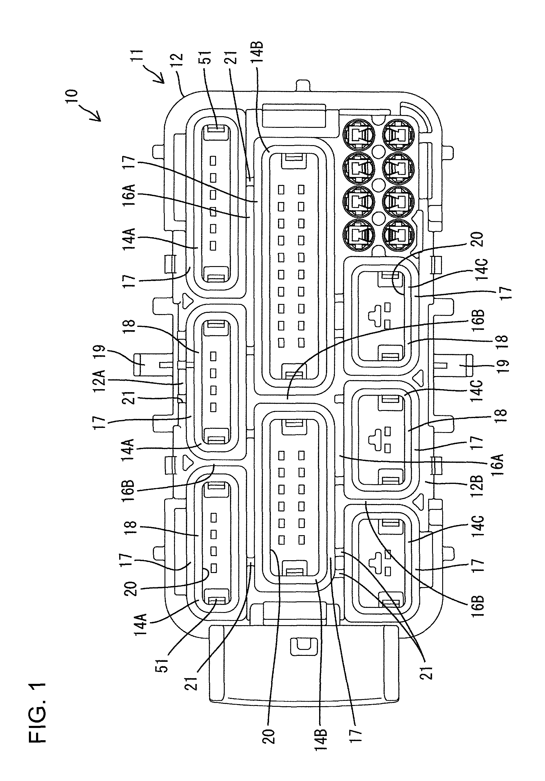
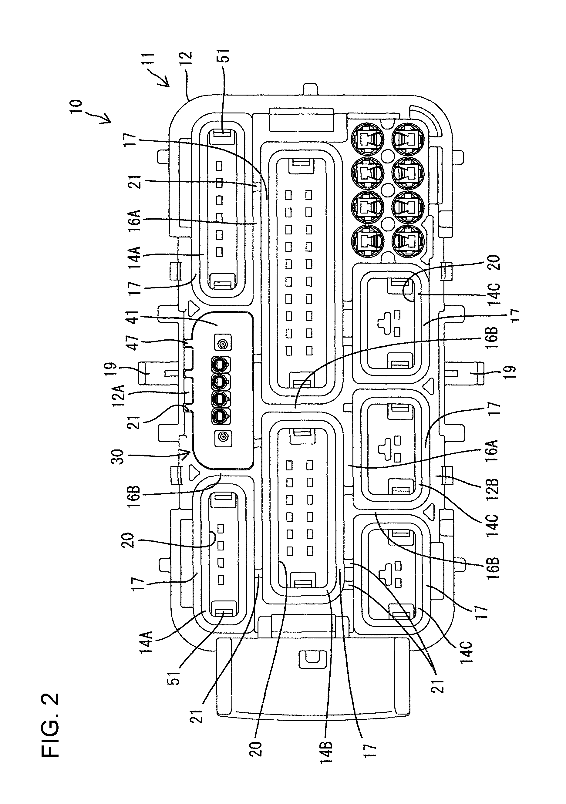
[0026]The first housing 10 has a frame 11 made of synthetic resin and a plurality of connector units 30. The frame 11 is approximately rectangular when is seen from the front (the configuration projected onto a plane orthogonal to a direction in which the first and second housings 10 and 60 are fit together). The frame 11 has an approximately quadrangular prism-shaped outer wall 12 (see FIGS. 1 and 2) and a front wall (see FIGS. 3 and 4) 13 covering a front end of a space surrounded by the outer wall 12. As shown in FIGS. 1 and 2, a plurality of tubular accommodation parts 14A, 14B, and 14C are formed in the space surrounded by the outer wall 12 and extend rearward from the front wall 13. Each tubular accommodation part 14A...


PUM


Abstract

A first housing (10) has a frame (11) with concave accommodation portions (20). A sub-connector (31) with female terminal fittings (33) is accommodated in the concave accommodation portions (20). A collective rubber stopper (36) is accommodated inside the concave accommodation portions (20) to seal a gap between a peripheral surface of an electric wire (34) pulled out of the sub-connector (31) and an inner peripheral surface of each concave accommodation portion (20). A first cam follower (19) is formed on an outer surface of the frame (11) and can engage an operation member (80). The frame (11) has an outer wall (12) defining an outer surface thereof where the first cam follower (19) is formed and an inner wall (18) separated from the outer wall part (12) via separated spaces (17) and constructing the inner peripheral surface of each concave accommodation portions (20).

Description

BACKGROUND OF THE INVENTION[0001]1. Field of the Invention[0002]The invention relates to a connector.[0003]2. Description of the Related Art[0004]U.S. Pat. No. 7,448,908 discloses a waterproof connector with first and second housings that are fit together by operating a lever. The first housing has a frame with concave accommodation parts and sub-connectors having terminal fittings are accommodated in the concave accommodation parts. A collective rubber stopper is accommodated in the concave accommodation parts to seal gaps between electric wires pulled out of the sub-connectors and inner peripheries of the concave accommodation parts. An engaging part is formed on the outer surface of the frame and defines a supporting shaft for pivotably supporting the lever. The lever has a cam groove that engages a cam follower of the second housing. Pivoting the lever generates a cam action between the cam groove and the cam follower that urges the first and second housings together.[0005]Fit-o...

Claims


Application Information

Patent Timeline
Patent Type & Authority Patents(United States)
IPC IPC(8): H01R13/52
CPCH01R13/521H01R13/5208
Inventor KATAOKA, SHIGETO
Owner SUMITOMO WIRING SYST LTD
Why Eureka
Try Eureka