Seal structure for electronic control device

a technology of electronic control device and sealing structure, which is applied in the direction of electrical apparatus casing/cabinet/drawer, hermetically sealed casing, coupling device connection, etc., can solve the problems of water entering the outside, the sealant cannot be extended enough, etc., and achieve the effect of preventing deterioration in seal performan

Active Publication Date: 2016-03-22
HITACHI ASTEMO LTD
View PDF10 Cites 3 Cited by
  • Summary
  • Abstract
  • Description
  • Claims
  • Application Information

AI Technical Summary

Benefits of technology

[0009]The present invention has been made in view of the foregoing technical problem. It is an object of the present invention to provide a seal structure for an electronic control device, capable of preventing deterioration in seal performance while allowing downsizing of the electronic control device.
[0011]It is possible according to the present invention to, even when the connector is displaced in position relative to the base member, prevent deterioration in seal performance at the junction between the connector seal surface and the seal groove.

Problems solved by technology

At such a junction between the connector seal surface and the seal groove, the sealant spreads over and covers the lower surface of the connector, without being pushed into the seal groove by the seal protrusion, so that it becomes impossible to ensure the sufficient seal length of the sealant in the protrusion-groove seal.
This results in the entry of water etc. from the outside due to deterioration in seal performance.

Method used


Image

  • Seal structure for electronic control device
  • Seal structure for electronic control device
  • Seal structure for electronic control device

Examples


Embodiment Construction

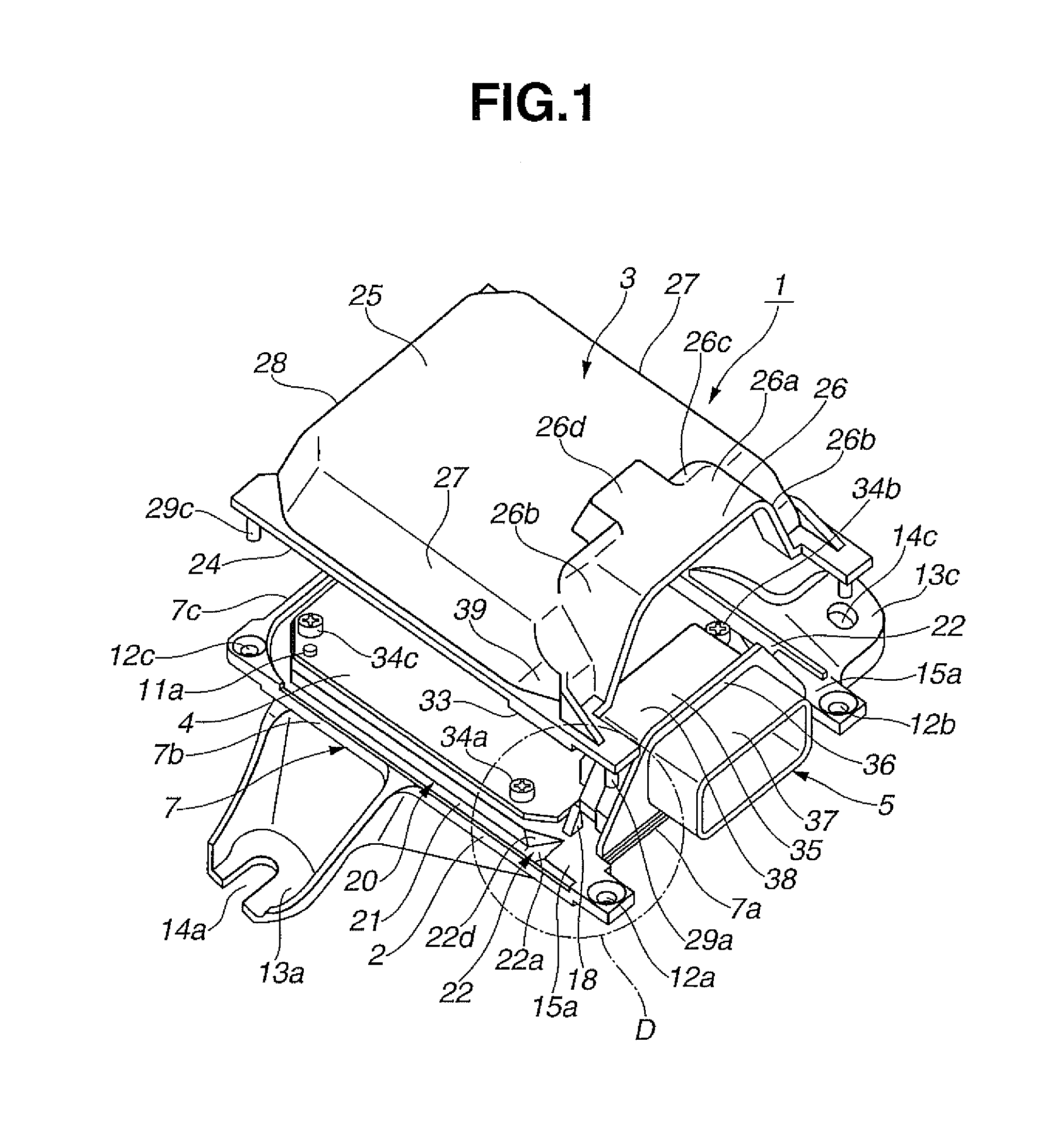
[0023]A seal structure for an electronic control device according to one embodiment of the present invention will be described below with reference to the drawings. The electronic control device is herein configured as an engine control unit of a vehicle. As mentioned above, the terms “front”, “rear”, “upper” and “lower” are used for illustration purposes and are not intended to limit the scope of the present invention. In the present embodiment, the upper-lower direction of the electronic control device (the thickness direction of the electronic control device) corresponds to the upper-lower direction of FIG. 1. However, this direction does not necessarily correspond to a vertical direction of the vehicle under a state that the electronic control device has been mounted on the vehicle. When the electronic control device is mounted in vertical orientation on the vehicle, for example, the upper-lower direction of the electronic control device is in agreement with the front-rear direc...


PUM


Abstract

Disclosed is a seal structure for an electronic control device where a circuit board is accommodated in a housing with a connector attached to the circuit board and held between base and cover members of the housing. The seal structure includes a connector seal surface formed on a front end portion of the base member, a seal material arranged between the connector seal surface and the connector, a seal groove formed in an outer peripheral portion other than the front end portion of the base member, a seal protrusion formed on the cover member and engaged in the seal groove, and a sealant filled between the seal groove and the seal protrusion. Longitudinal end regions of the connector seal surface are extended in a width direction of the connector. Longitudinal end regions of the seal groove are connected perpendicular to the respective end regions of the connector seal surface.

Description

BACKGROUND OF THE INVENTION[0001]The present invention relates to a seal structure suitable for an electronic control device such as engine control unit or automatic transmission control unit. Hereinafter, the terms “upper” and “lower” are used with respect to the height (thickness) direction of the electronic control device; and the terms “front” and “rear” are used with respect to the insertion direction of a connector of the electronic control device for connection to an external device. It should however be noted that these terms are used for illustration purposes and are not intended to limit the scope of the present invention.[0002]Japanese Laid-Open Patent Publication No. 2014-049702 discloses a seal structure for an electronic control device such as engine control unit or automatic transmission control unit. The electronic control device includes a housing having a base member and a cover member fitted on an upper side of the base member, a circuit board accommodated in an i...

Claims


Application Information

Patent Timeline
Patent Type & Authority Patents(United States)
IPC IPC(8): H01R13/52H01R24/76H05K5/06H01R13/66
CPCH05K5/063H01R13/5213H01R13/6658H01R24/76H05K5/0052H05K5/0069
Inventor ICHIKAWA, EIJI
Owner HITACHI ASTEMO LTD
Why Eureka
Try Eureka