LED lighting system with accurate current control

a technology of led lighting and current control, applied in the field of electrical and lighting, can solve the problems of high cost to improve the sound path, difficult or impossible to achieve the desired amount of charge for an active time period of led current isub>led/sub>to an led system, and limited to the exactness

Active Publication Date: 2013-07-16
SIGNIFY HLDG BV
View PDF235 Cites 102 Cited by
  • Summary
  • Abstract
  • Description
  • Claims
  • Application Information

AI Technical Summary

Problems solved by technology

However, due to limitations of quantizing charge in discrete time, providing an ideal desired amount of charge for an active time period for LED current ILED to an LED system is very hard or impossible to achieve.
The inherent problem of quantizing cycles of charge is that it is limited to the exactness of the amount of charge of LED current ILED being provided to the LED system due to the fact that charge is quantized in discrete amounts based on discrete time.
Furthermore, operation below a PWM frequency of 20 kHz for pulsing the enable input signal has the potential to create audio tones due to acoustic behavior of magnetic material, which is undesirable and can lead to higher cost to ameliorate the sound path.
On the other hand, an overly fast PWM operation frequency for pulsing the enable input signal runs into a problem with the start-up and shut down of the current controller.
At high PWM operation frequencies, many other negative effects that the dimmable LED lighting system may encounter are the non-uniform dimming control, unpredictable control, and non-linear behavior.
In applications with multiple LED colors, the balance between a slow and fast PWM operation frequency is important to the resulting color, and these issues severely limit the ability to provide a desired resulting color.
However, the use of delta-sigma modulation would be impractical with the slow behavior of the controller.

Method used


Image

  • LED lighting system with accurate current control
  • LED lighting system with accurate current control
  • LED lighting system with accurate current control

Examples


Embodiment Construction

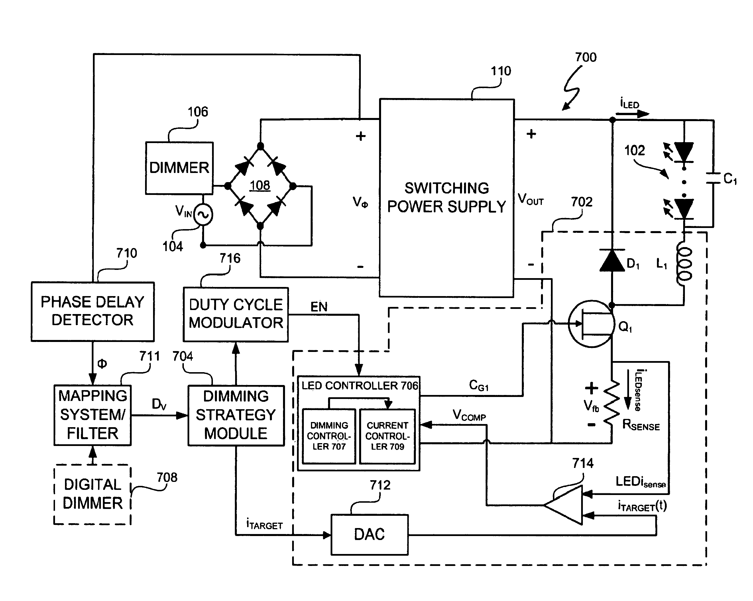
[0054]A light emitting diode (LED) lighting system includes an LED controller to accurately control a current in an LED system. The LED controller includes components to calculate, based on the current and an active time period of an LED current time period, an actual charge amount delivered to the LED system wherein the LED current time period is duty cycle modulated at a rate of greater than fifty (50) Hz and to utilize the actual charge amount to modify and provide a desired target charge amount to be delivered during a future active time period of the LED current time period. The LED system further has components to calculate for an active time period of the LED current time period an actual charge amount delivered to the LED system and also has components to compare the actual charge amount to a desired charge amount for the active time period of the LED current time period and compensate for a difference between the actual charge amount and the desired charge amount during the...


PUM


Abstract

A light emitting diode (LED) lighting system and method are disclosed. The LED lighting system and method include an LED controller to accurately control a current in an LED system. The LED controller includes components to calculate, based on the current and an active time period of an LED current time period, an actual charge amount delivered to the LED system wherein the LED current time period is duty cycle, modulated at a rate of greater than fifty (50) Hz and to utilize the actual charge amount to modify and provide a desired target charge amount to be delivered during a future active time period of the LED current time period. The LED system and method further involve components to compare the actual charge amount to a desired charge amount for the active time period and compensate for a difference between the actual charge amount and the desired charge amount during the future active time period.

Description

CROSS REFERENCE TO RELATED APPLICATIONS[0001]This application claims the benefit under 35 U.S.C. §119(e) and 37 C.F.R. §1.78 of U.S. Provisional Patent Application No. 61 / 092,842, filed Aug. 29, 2008 and entitled “Duty Cycle Dimming”.[0002]U.S. Provisional Application No. 60 / 909,458, entitled “Ballast for Light Emitting Diode Light Sources,” inventor John L. Melanson, and filed on Apr. 1, 2007 describes exemplary methods and systems and is incorporated by reference in its entirety. Referred to herein as “Melanson I”.[0003]U.S. patent application Ser. No. 12 / 047,249, entitled “Ballast for Light Emitting Diode Light Sources,” inventor John L. Melanson, and filed on Mar. 12, 2008 describes exemplary methods and systems and is incorporated by reference in its entirety. Referred to herein as “Melanson II”.[0004]U.S. patent application Ser. No. 12 / 047,269, entitled “Lighting System with Power Factor Correction Control Data Determined from a Phase Modulated Signal,” inventor John L. Melans...

Claims


Application Information

Patent Timeline
Patent Type & Authority Patents(United States)
IPC IPC(8): H05B37/02H05B44/00
CPCH05B33/0839H05B33/086H05B33/0848H05B33/0818Y02B20/347H05B45/14H05B45/20H05B45/327Y02B20/30H05B45/3725H05B45/00H05B45/37
Inventor MELANSON, JOHN LAURENCE
Owner SIGNIFY HLDG BV
Why Eureka
Try Eureka