Transcutaneous energy transfer module with integrated conversion circuitry

a technology of energy transfer module and conversion circuit, which is applied in the field of transcutaneous energy transfer device, can solve the problems of affecting the uniform power applied to the equipment, affecting the effect of the desired effect of equipment uniformity, and inducing the heating of components, and achieves the effect of high power outpu

Inactive Publication Date: 2013-07-16
ABIOMED
View PDF44 Cites 59 Cited by
  • Summary
  • Abstract
  • Description
  • Claims
  • Application Information

AI Technical Summary

Benefits of technology

This patent describes a technology related to wireless power transmission through the skin (known as transcutaneous energy transfer). A new design was created called a secondary coil module which receives a strong magnetic field generated by a nearby primary coil and converts it into a lower voltage electric signals. These signals are then sent out to power other electronic devices inside the body. The main benefit of this innovation is its ability to generate higher levels of power with smaller components, making it more efficient and easier to use compared to previous designs.

Problems solved by technology

The technical problem addressed in this patent text is the heating of components in the secondary coil of a TET system caused by the magnetic field induced by the current in the coil. This can lead to damage or discomfort to the patient and interfere with the performance of the device. The solution presented is to mount the components inside the secondary coil to minimize heating, but this can still result in significant heating, so there is a need for an improved technique to reduce heating while still distributing power to distributed implanted devices.

Method used


Image

  • Transcutaneous energy transfer module with integrated conversion circuitry
  • Transcutaneous energy transfer module with integrated conversion circuitry
  • Transcutaneous energy transfer module with integrated conversion circuitry

Examples


Embodiment Construction

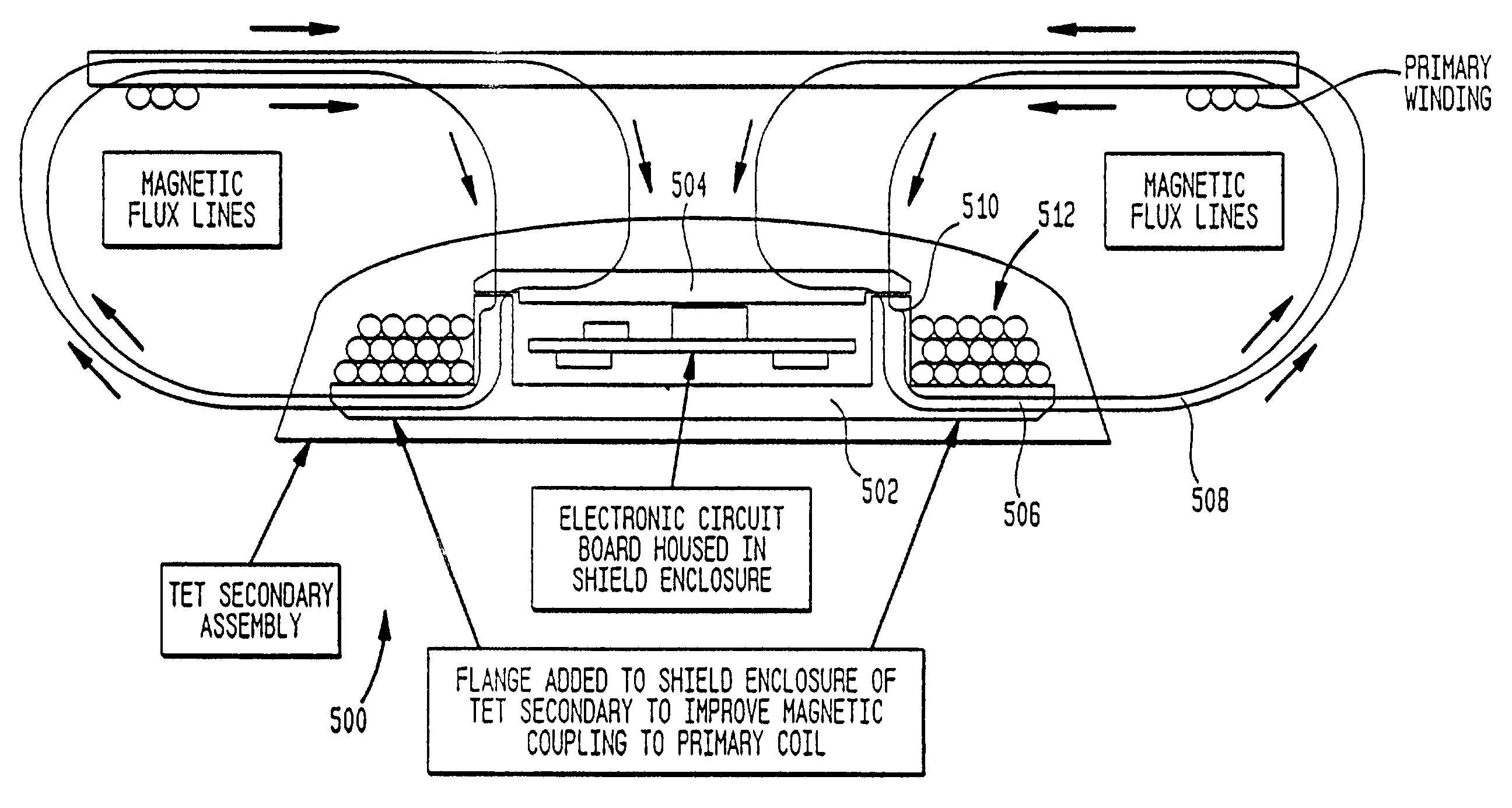
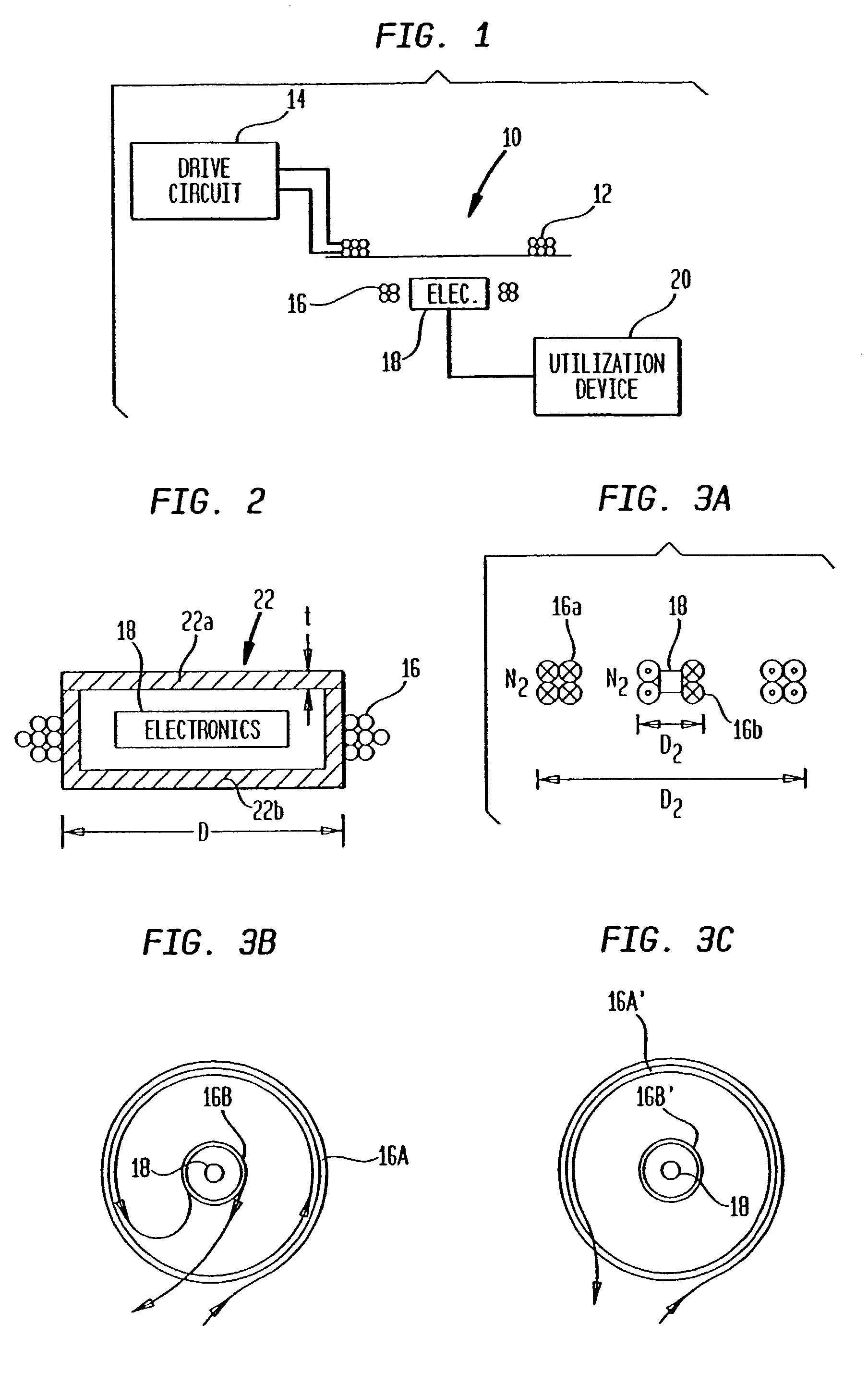
[0024]Referring to FIG. 1, an exemplary TET system 10 is shown which includes a primary coil 12 connected to receive an alternating drive signal from an appropriate drive circuit 14 and a transcutaneously mounted secondary coil 16 having signal processing electronics 18 mounted therein. The signal from electronics 18 is applied to operate a utilization device 20 which may for example be a blood pump, artificial heart, defibrillator, or other implanted device requiring power or other signals applied thereto.

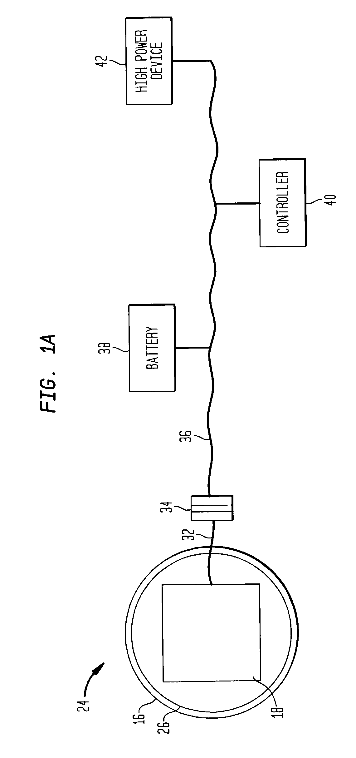
[0025]For a number of reasons, it is desirable for electronics 18 to include power conditioning circuitry—such as, for example, rectifying or converting circuitry, regulating circuitry, monitoring circuitry, or other circuitry known for use in modifying power signals, within a secondary coil module. In the exemplary system diagram of FIG. 1A, a secondary coil module 24 is illustrated as including an inner housing 26 with the secondary coil 16 provided outside the inner housing. Se...


PUM

PropertyMeasurementUnit
Poweraaaaaaaaaa
Poweraaaaaaaaaa
Poweraaaaaaaaaa

Abstract

An implantable transcutaneous energy transfer device secondary coil module includes a housing, a secondary coil, power conditioning circuitry, and a low voltage, high power connector. The transcutaneous energy transfer secondary coil is disposed outside the housing and is configured to receive a time-varying magnetic field provided by a transcutaneous energy transfer primary coil, and to convert the time-varying magnetic field into a high voltage, alternating current electric signal within the coil. The power conditioning circuitry is mounted within the housing and is electrically coupled to the secondary coil. The power conditioning circuitry including electronics for converting the high voltage, alternating current electric signal from the secondary coil into a high power, low voltage direct current electric signal. The low voltage, high power connector electrically coupled to the power conditioning circuitry and extending outside the housing for connecting the secondary coil module to a power bus for delivering power to implanted devices.

Description


Claims


Application Information

Patent Timeline
Owner ABIOMED
Why Eureka
Try Eureka