High-speed acrylic electroactive polymer transducers

Inactive Publication Date: 2007-08-30
SRI INTERNATIONAL +1
View PDF56 Cites 70 Cited by
  • Summary
  • Abstract
  • Description
  • Claims
  • Application Information

AI Technical Summary

Benefits of technology

[0058] Regarding methodology, the subject methods may include each of the mechanical activities associated with use of the devices describe as well as electrical activity. As such, methodology implicit to the use of the devices described forms part of the invention. Such methodology may include that associated with running acrylic based EPAM™ transducers as motors or generators at higher frequencies or power output/generation levels that

Problems solved by technology

One limitation of know actuators has been tied to the elastic dielectric material selected for use.
However, prior extensive testing has lead those with skill in the art to believe that acrylic-based E

Method used


Image

  • High-speed acrylic electroactive polymer transducers
  • High-speed acrylic electroactive polymer transducers
  • High-speed acrylic electroactive polymer transducers

Examples


Embodiment Construction

[0092] Various exemplary embodiments of the invention are described below. A number of actuator / transducer embodiments are first described. Next, systems optionally incorporating such devices are described. They are provided to illustrate broadly applicable aspects of the present invention.

Frustum Transducers

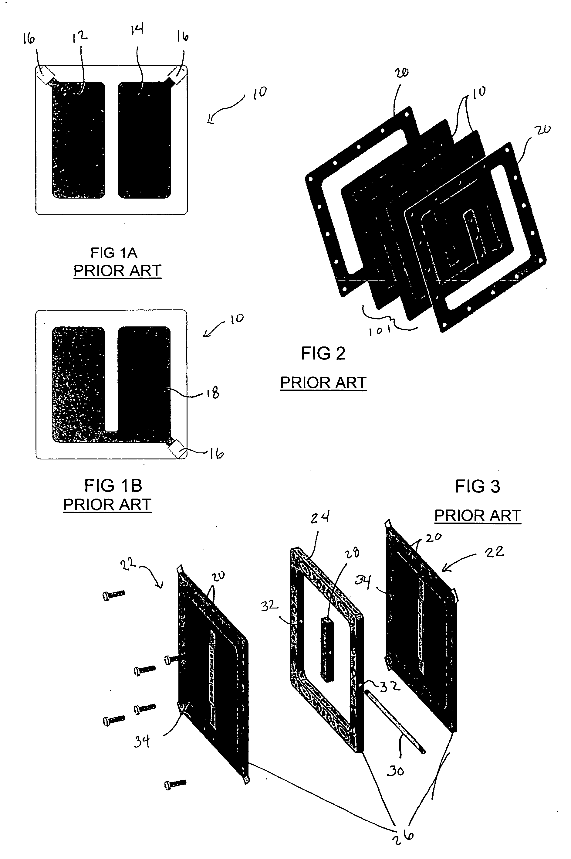
[0093]FIGS. 1A and 1B show opposite sides of an EPAM™ layer 10. The layer comprises dielectric polymer sandwiched between elastic thin film electrodes. FIG. 1A shows the side of the layer patterned with “hot” electrodes 12 and 14. Each electrode is connected to a lead 16. FIG. 1B shows the opposite side of layer 10 patterned with a common “ground” electrode 18 connected to a single lead 16.

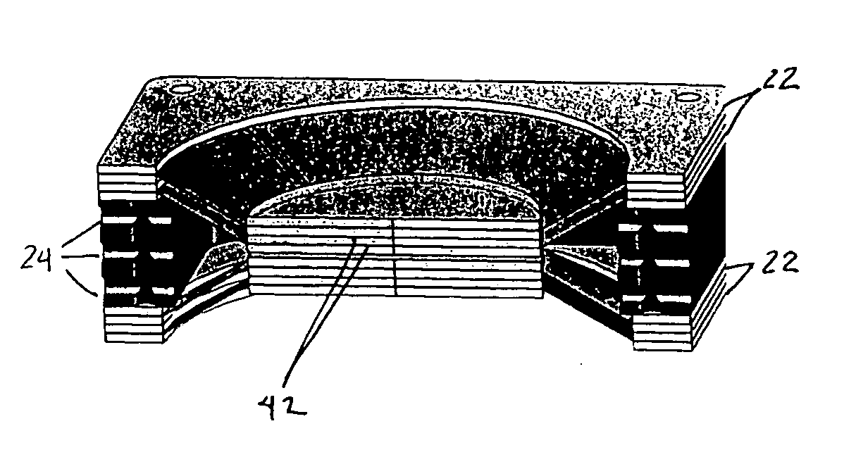
[0094] As shown in FIG. 2, multiple film layers 10 are stacked and held in a stretched state within frame pieces 20. A number of individual EPAM™ layers 10 are advantageously stacked to form a compound layer 10′. Doing so amplifies the force potential of the system. The number of layers st...


PUM


Abstract

Devices employing electroactive polymer actuators are disclosed. Acrylic dielectric material based actuators are optionally provided in which architectures are presented that allow for improved power output as compared with other known acrylic dielectric material based transducers. Such technology may be applied in motor-driven applications, lightweight flight applications and lighting applications among others.

Description

CROSS-REFERENCE [0001] This application claims the benefit of U.S. patent application Ser. No. 11 / 085,798, entitled, “Electroactive Polymer Actuated Devices,” filed Mar. 21, 2005, and U.S. patent application Ser. No. 11 / 085,804, entitled “High-Performance Electroactive Polymer Transducers,” filed Mar. 21, 2005, incorporated herein by reference in their entirety.BACKGROUND [0002] A tremendous variety of devices used today rely on actuators of one sort or another to convert electrical energy to mechanical energy. The actuators “give life” to these products, putting them in motion. Conversely, many power generation applications operate by converting mechanical action into electrical energy. Employed to harvest mechanical energy in this fashion, the same type of actuator may be referred to as a generator. Likewise, when the structure is employed to convert physical stimulus such as vibration or pressure into an electrical signal for measurement purposes, it may be referred to as a trans...

Claims


Application Information

Patent Timeline
IPC IPC(8): H02N2/00
CPCH01L41/0986H02N2/046H01L41/193H10N30/206H10N30/857
Inventor HEIM, JONATHAN R.PELRINE, RONALD EDWARDKORNBLUH, ROYSMITH, JONATHAN A.
Owner SRI INTERNATIONAL
Why Eureka
Try Eureka