
Apparatus for performing an electrosurgical procedure

a technology for electrosurgical procedures and apparatuses, applied in the field of electrosurgical apparatuses, can solve the problems of preventing effective transfer of the desired closure force at the jaw members, unintentional or unwanted bending or flexing of the shaft, and reducing the operative li

Active Publication Date: 2013-07-23
TYCO HEALTHCARE GRP LP
View PDF128 Cites 113 Cited by
  • Summary
  • Abstract
  • Description
  • Claims
  • Application Information

AI Technical Summary

Benefits of technology

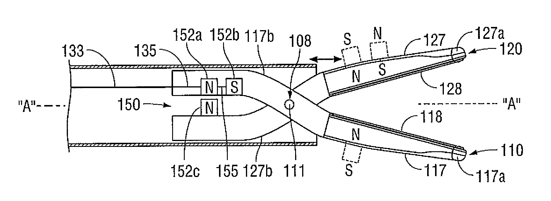
The present invention provides an endoscopic forceps that can be controlled using a magnetic actuation mechanism. The forceps have a housing with a shaft, and a pair of first and second jaw members that are pivotably connected to each other and movable relative to each other. The first and second jaw members can be opened and closed by the magnetic actuation mechanism. The forceps can be controlled by the magnetic actuation mechanism to grasp tissue between the jaw members. The technical effect of this invention is to provide a versatile and efficient tool for medical procedures that can be easily controlled and directed to the desired area.

Problems solved by technology

Or, under certain circumstances, the surgical environment may cause unintentional or unwanted bending or flexing of the shaft, such as, for example, in the instance where the shaft is a component of a catheter-based electrosurgical forceps.
As can be appreciated, when the shaft is bent or deformed (either intentionally or unintentionally) the frictional losses associated with drive rod translating through the shaft are transferred to the spring in the housing, which, in turn, may diminish, impede and / or prevent effective transfer of the desired closure force that is needed at the jaw members.
Moreover, the frictional losses may also lessen the operative life of the spring, which, in turn, ultimately lessens the operative life of the electrosurgical instrument.

Method used


Image

  • Apparatus for performing an electrosurgical procedure
  • Apparatus for performing an electrosurgical procedure
  • Apparatus for performing an electrosurgical procedure

Examples


Embodiment Construction

[0016]Detailed embodiments of the present disclosure are disclosed herein; however, the disclosed embodiments are merely examples of the disclosure, which may be embodied in various forms. Therefore, specific structural and functional details disclosed herein are not to be interpreted as limiting, but merely as a basis for the claims and as a representative basis for teaching one skilled in the art to variously employ the present disclosure in virtually any appropriately detailed structure.

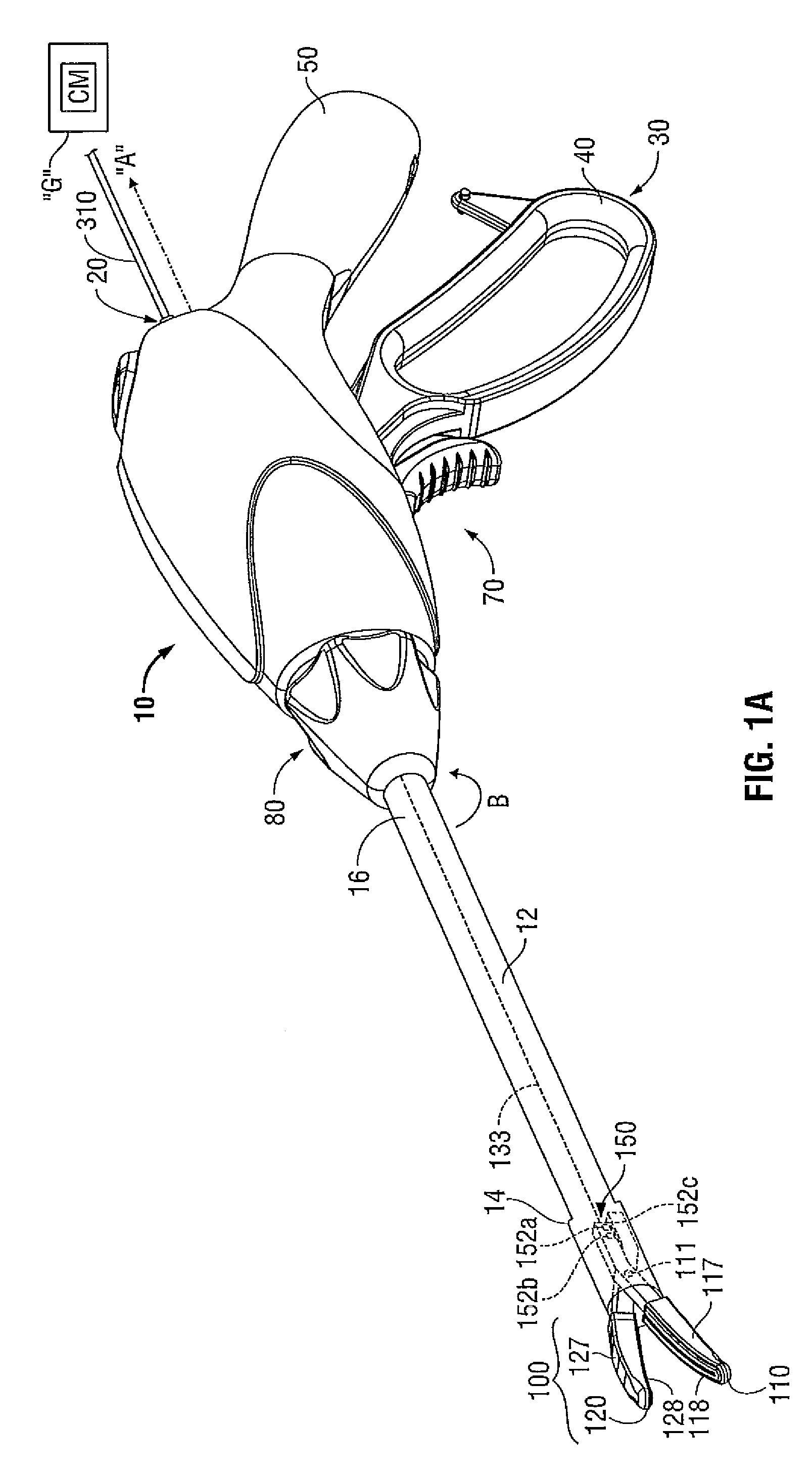
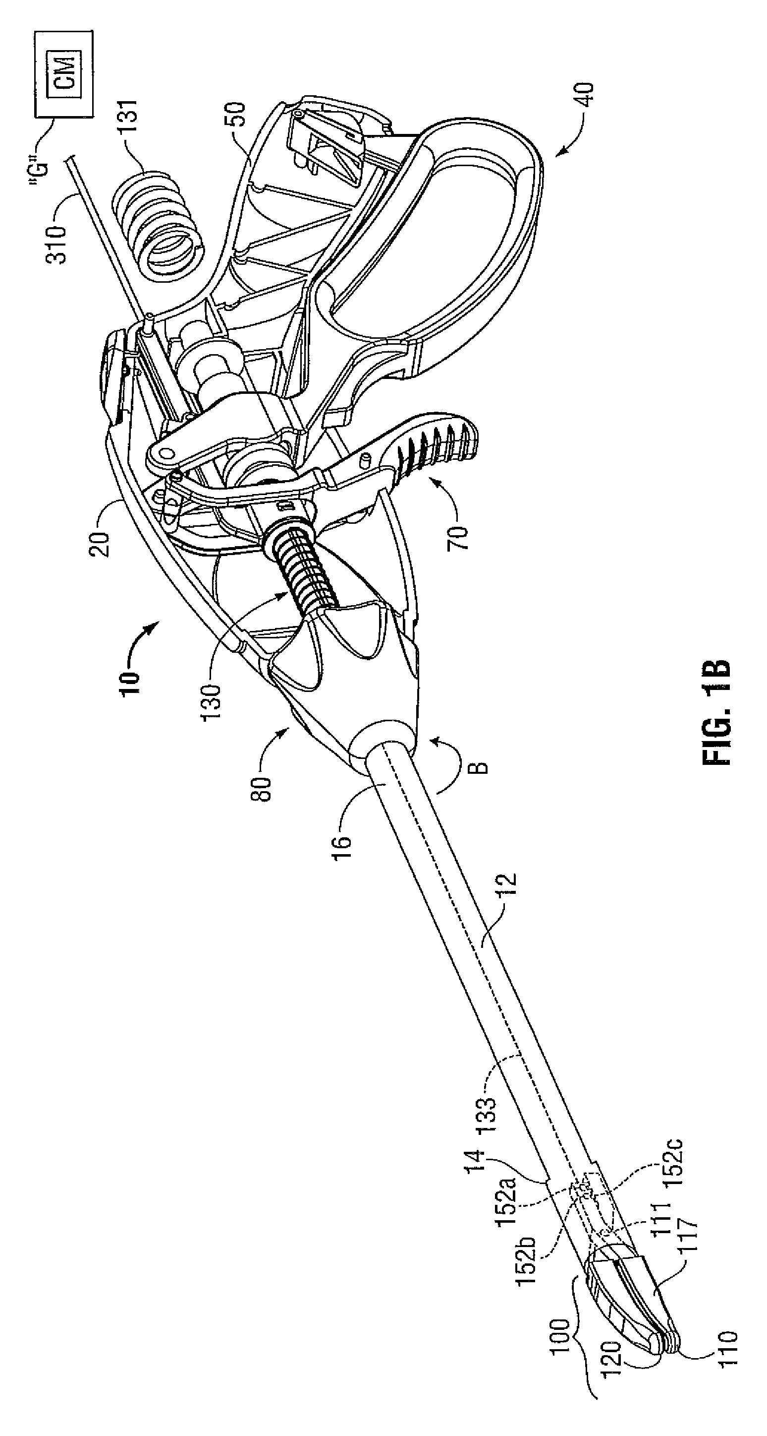
[0017]With reference to FIGS. 1A and 1B, an illustrative embodiment of an electrosurgical apparatus, e.g., a bipolar forceps 10 (forceps 10) is shown. Forceps 10 is operatively and selectively coupled to an electrosurgical generator (“G”) for performing an electrosurgical procedure. As noted above, an electrosurgical procedure may include sealing, cutting, cauterizing, coagulating, desiccating, and fulgurating tissue all of which may employ RF energy. The electrosurgical generator “G” may be confi...


PUM


Abstract

An endoscopic forceps is provided and includes a housing having a shaft that extends therefrom. An end effector assembly is operatively connected to a distal end of the shaft and includes a pair of first and second jaw members that are pivotably coupled to one another and movable relative to one another. The first and second jaw members are disposed in a first configuration, wherein the first and second jaw members are disposed in spaced relation relative to one another, to a second configuration, wherein the first and second jaw members cooperate to grasp tissue therebetween. A magnetic actuation mechanism is operably coupled to one or both of the first and second jaw members and configured to generate opposing magnetic fields on each of the first jaw and second jaw members to actuate the first and second jaw members between the first and second configurations.

Description

BACKGROUND[0001]1. Technical Field[0002]The present disclosure relates to an apparatus for performing an electrosurgical procedure. More particularly, the present disclosure relates to an electrosurgical apparatus including an end effector assembly having a pair of jaw members that provide a mechanical advantage at the end effector.[0003]2. Description of Related Art[0004]Electrosurgical instruments, e.g., electrosurgical forceps (open or closed type), are well known in the medical arts and typically include a housing, a handle assembly, a shaft and an end effector assembly attached to a distal end of the shaft. The end effector includes jaw members configured to manipulate tissue (e.g., grasp and seal tissue). Typically, the electrosurgical forceps utilizes both mechanical clamping action and electrical energy to effect hemostasis by heating the tissue and blood vessels to coagulate, cauterize, seal, cut, desiccate, and / or fulgurate tissue. Typically, one or more driving mechanisms...

Claims


Application Information

Patent Timeline
Patent Type & Authority Patents(United States)
IPC IPC(8): A61B17/00A61B18/14
CPCA61B17/29A61B18/1445A61B2017/00398A61B2017/00876A61B2018/0063A61B2017/2932
Inventor ROY, JEFFREY M.ALLEN, IV, JAMES D.
Owner TYCO HEALTHCARE GRP LP
Learn More