Unlock instant, AI-driven research and patent intelligence for your innovation.

Method for automatically identifying scan region boundary

a scanning region and automatic identification technology, applied in the field of scanning methods, can solve the problems of inapplicability of the above-mentioned operation method to small and portable scanners without auxiliary equipment, inability of the above-mentioned operation method to determine the left and right boundary of reflective documents, and difficulty in unified background primary color of prior scanning devices

Inactive Publication Date: 2013-07-23
QISDA SUZHOU
View PDF16 Cites 1 Cited by
  • Summary
  • Abstract
  • Description
  • Claims
  • Application Information

AI Technical Summary

Benefits of technology

The patent describes a method for determining the boundary of a scan document by analyzing the brightness of points in the scan data. The method is not affected by environmental factors and can be used with transparent and reflective documents. It simplifies the scanning device and improves automatic performance. The method uses continual points as a basis of correction to avoid errors in determination. Overall, the method provides a reliable and efficient way to determine the boundary of a scan document.

Problems solved by technology

The boundary setting for implementing the above operation method is not applicable to small and portable scanners which are not equipped with the auxiliary apparatus, such as computers.
With the existence of the backlight element, the above method for determining the left and the right boundary of the reflective document is not applicable.
Furthermore, it is still very difficult for the prior scanning devices to have a unified background primary color, so any minute change in the background color would affect the accuracy in the determination of the scan boundary based on the unified background primary color.

Method used


Image

  • Method for automatically identifying scan region boundary
  • Method for automatically identifying scan region boundary
  • Method for automatically identifying scan region boundary

Examples


Embodiment Construction

[0032]The method of automatically identifying the scan region boundary is applicable to confirming the scan boundary during the scanning of a reflective document or a transparent document. In scanning a document under a non-unified background, the methods of embodiments of the disclosure precisely confirm the scan boundary of the scan document, particularly, the left boundary and the right boundary. The technology of embodiments of the disclosure is exemplified by the drawings and the disclosures below.

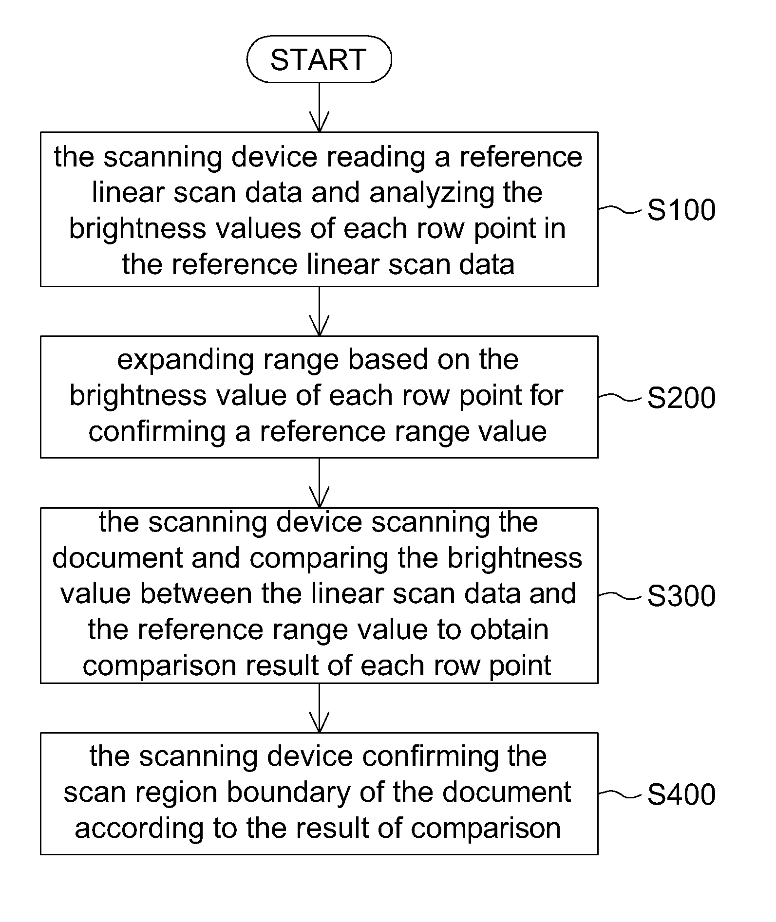
[0033]As indicated in FIG. 1, the scanning device can be realized by a multi-functional scanner capable of scanning reflective and transparent document. A backlight element is disposed on opposite side of the scan module. With the existence of the backlight element, the scan background of the scan module is a non-unified multi-color background. At step S100, the scanning device reads a reference linear scan data and analyzes the brightness values of each row point in the reference lin...


PUM


Abstract

A method of automatically identifying a scan region boundary, used for scanning a document under a non-unified background, includes: reading a reference linear scan data by a scanning device, the scanning device analyzing brightness values in each row of the reference linear scan data and determining a reference range value according to the brightness values in each row; and during scanning a document, the scanning device comparing brightness values of a linear scan data with the reference range value so as to determine the scan region boundary. The method confirms the scan boundary of a document and is not subjected to a backlight element or a document carrier. The method identifies the boundary of a document under a non-unified background, is applicable to scanning transparent and reflective documents and has strong resistance against environmental interference, not only simplifying the scanning device but also enhancing the automatic performance.

Description

[0001]This application claims the benefit of People's Republic of China application Serial No. 200910176303.8, filed Sep. 12, 2009, the subject matter of which is incorporated herein by reference.BACKGROUND OF THE DISCLOSURE[0002]1. Field of the Disclosure[0003]The disclosure relates in general to a scanning method of a scanning device, and more particularly to a method of automatically identifying a scan region boundary for non-unified background and with the capability of overcoming backlight interference.[0004]2. Description of the Related Art[0005]Most of the scanning devices adopt user / manual browsing and boundary setting for confirming a scan boundary of a document. The setting of document boundary includes operations such as marking and width setting, which need to be implemented via the display device and the input device. The boundary setting for implementing the above operation method is not applicable to small and portable scanners which are not equipped with the auxiliar...

Claims


Application Information

Patent Timeline
Patent Type & Authority Patents(United States)
IPC IPC(8): H04N1/04
CPCH04N1/00795H04N1/00816H04N1/38
Inventor GUO, XIAN-QIANG
Owner QISDA SUZHOU