Power transmitting system through cables for airborne wind-type power generation applications

Inactive Publication Date: 2013-07-30
VERGNANO GIOVANNI
View PDF6 Cites 1 Cited by
  • Summary
  • Abstract
  • Description
  • Claims
  • Application Information

AI Technical Summary

Benefits of technology

The patent text allows for various modifications to be made to the described invention without changing the scope of the claim. This applies to regular changes in shape, size, arrangements, and parts with equivalent functions.

Problems solved by technology

The generation of energy at an upper level, where strong and constant winds blow, has always encountered a difficulty linked to the weight of systems designed for such purpose.
Regarding the generator, so far its placement has been thought at an upper level due to the difficulties of transferring generated energy to the ground.
The generator weight therefore has remained the main obstacle to the development of wind generation at an upper level.

Method used


Image

  • Power transmitting system through cables for airborne wind-type power generation applications
  • Power transmitting system through cables for airborne wind-type power generation applications
  • Power transmitting system through cables for airborne wind-type power generation applications

Examples


Embodiment Construction

[0017]As stated above, the present invention uses the typical traditional pulley-type transmissions, where size and mass of pulleys and belts depend on friction to be obtained, that must be greater than the forces to be transmitted. The big winches used on sailing boats, coupled with fiber cables with an optimum weight / resistance ratio, are a good example of a discontinuous energy transmission, where the necessary friction on the drum is obtained with many cable windings.

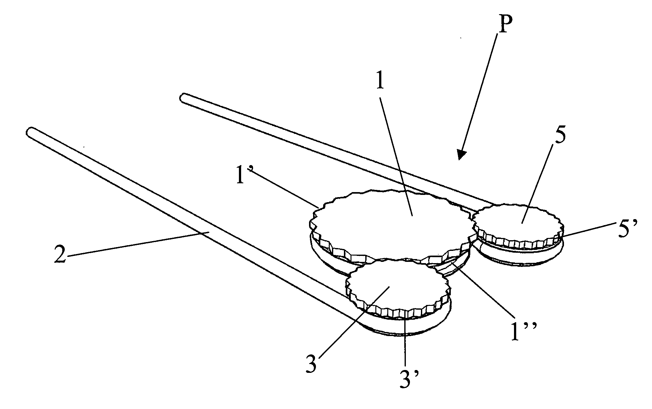
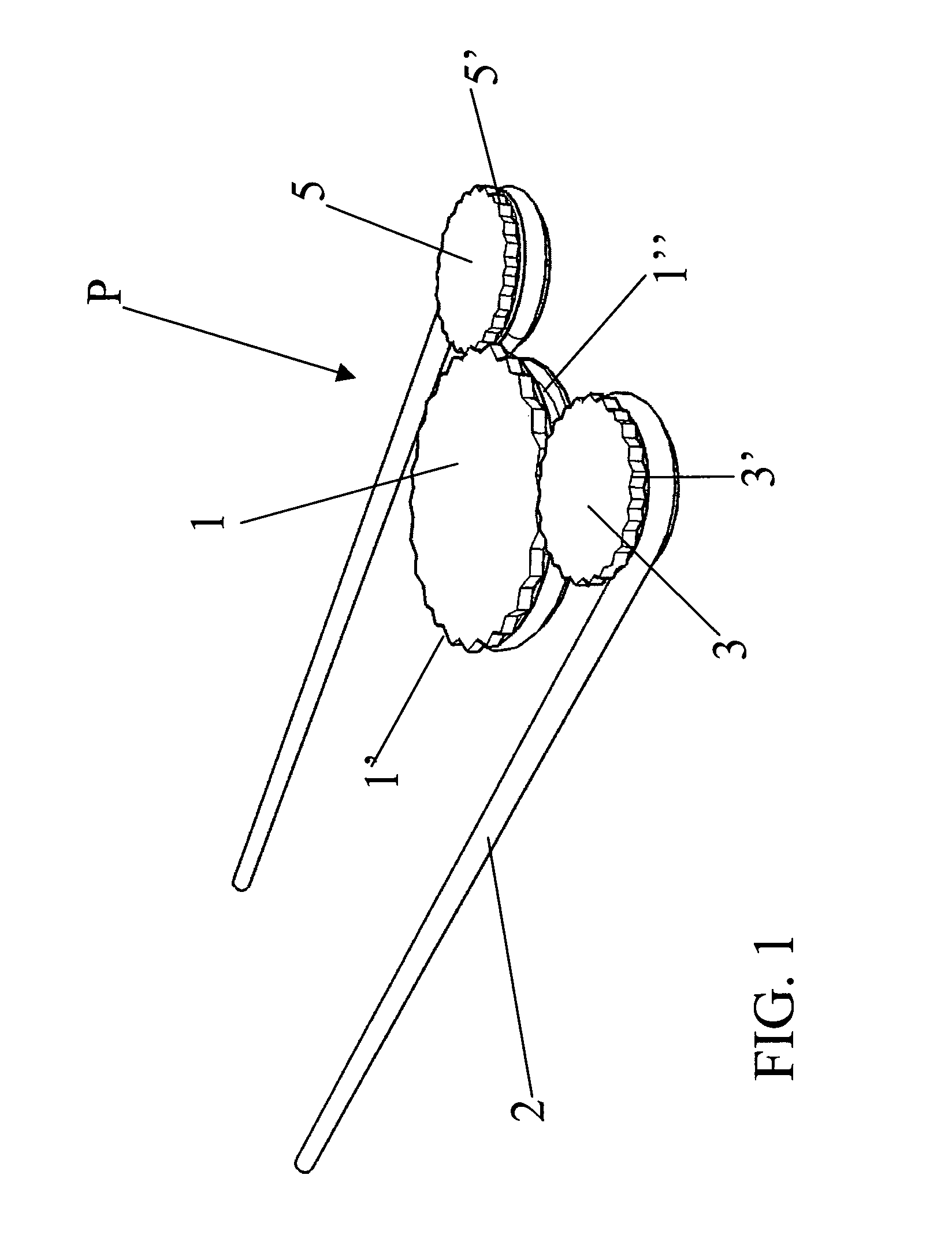
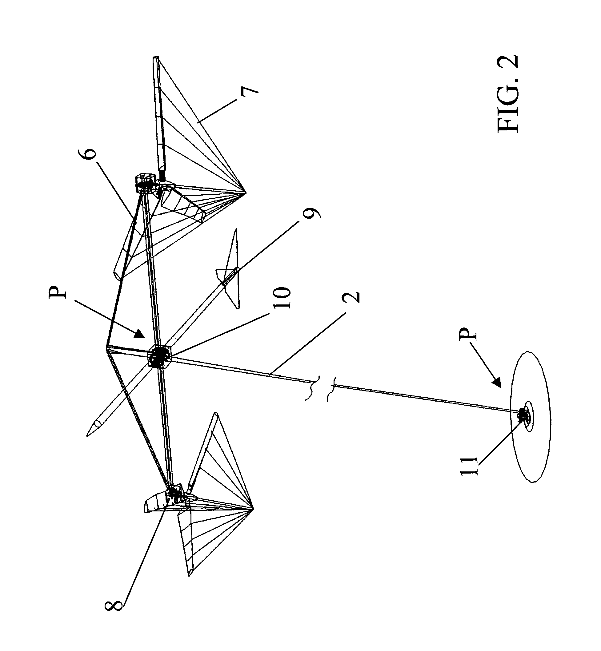
[0018]In order to increase the friction surfaces between pulleys and cable, without needing many windings on the same rotary element, and in order to give continuity to energy transmission through cables, it is necessary to modify the system of winches by creating special, mutually mechanically interconnected pulleys (FIG. 1), with a high-resistance cable with pre-established length that is closed as a loop (like in the application in FIG. 2).

[0019]The principle of power transmission is similar to the one of a bicyc...


PUM

PropertyMeasurementUnit
Timeaaaaaaaaaa
Flexibilityaaaaaaaaaa
Energyaaaaaaaaaa

Abstract

The present invention deals with a new system for transmitting energy through a cable and interconnected pulleys. The traditional power transmission through pulleys sizes the system of belts and friction surfaces depending on energy to be transmitted and is obtained through systems composed of a rotary element for every point of application and of a flexible element for the connection. In the proposed system, the flexible element is a high-resistance cable and friction on the rotary element is increased by using interconnected pulleys, which increase the cable friction surface allowing power transmissions without any sliding till the cable breaking point. The lightness of such system allows it to find optimum application in transmitting to ground all wind energy produced at an upper level. The system of interconnected pulleys is further applied to discontinuous tractions in the sailing field, replacing the traditionally used winches.

Description

CROSS-REFERENCE TO RELATED APPLICATIONS[0001]The present application is a national stage of International Patent Application No. PCT / IT2008 / 000699, titled “Power Transmitting System Through Cables for Airborne Wind-Type Power Generation and Sail Winch-Driving Applications,” filed Nov. 10, 2008, which claims priority from Italian Patent Application No. TO2007A000833 filed Nov. 21, 2007, the contents of which are incorporated in this disclosure by reference in their entirety.BACKGROUND OF THE INVENTION[0002]1. Field of the Invention[0003]The present invention refers to a power transmitting system through cables, in particular for wind-type power generation and sail winch-driving applications.[0004]2. Background Art[0005]The generation of energy at an upper level, where strong and constant winds blow, has always encountered a difficulty linked to the weight of systems designed for such purpose.[0006]One of the most complete studies about this subject has been made for the Skywindpower ...

Claims


Application Information

Patent Timeline
IPC IPC(8): F03D11/02F03D5/02
CPCB63H9/10B66D1/7415F03D11/02F16H55/38Y02E10/722F03D15/00F03D9/25F03D13/20F03D15/10Y02E10/72
Inventor VERGNANO, GIOVANNI
Owner VERGNANO GIOVANNI
Why Eureka
Try Eureka