
Modular power distribution assembly with multiple circuits

a technology of power distribution assembly and circuit, applied in the direction of coupling device connection, coupling device details, connection contact member material, etc., can solve the problems of complex modification of wall panels on site at the installation facility, affecting the provision of communications between panels, and affecting the effect of communication quality

Active Publication Date: 2013-07-30
BYRNE NORMAN R
View PDF16 Cites 29 Cited by
  • Summary
  • Abstract
  • Description
  • Claims
  • Application Information

AI Technical Summary

Benefits of technology

The patent text describes a system for providing electrical power and communication connections to modular office systems. The system uses modular wall panels that can be joined together in different configurations. However, existing systems have limitations in terms of the types of electrical circuits that can be used and the distance between electrical devices. The patent aims to address these limitations and provide a more flexible and convenient system for interconnecting electrical devices to utility power. The technical effects of the patent include the ability to use multiple circuit configurations with a single modular system, the provision of convenient interconnection of electrical devices to utility power, and the avoidance of custom modifications to the power system of wall panels. Additionally, the patent addresses the problem of insufficient room within a raceway to provide for junction blocks and electrical outlet receptacle blocks.

Problems solved by technology

However, these modular systems must not only allow for change in furniture configurations, but also must provide for convenient interconnection of electrical devices to utility power, regardless of the spacial configuration of the modular systems and resultant variable distances between electrical devices.
The problems associated with providing distribution of communications essentially correspond to the same problems existing with respect to distribution of conventional electrical power.
However, it is also apparent that to the extent reference is made herein to providing electrical outlets and electrical power connections for adjacent panels, the same issues exist with respect to providing communications among panels.
Under such circumstances, the interconnecting wiring becomes a significant problem.
Still further, modifications of wall panels on site at the installation facility is complex and may be relatively expensive.
In addition to the foregoing issues, problems can arise with respect to the use of junction blocks and the amount of room which may exist within a raceway.
Consequently, costly inventory of couplers must be maintained.
There is a distinct disadvantage in modern day systems, where several independent electrical circuits are needed in a wall panel system, with each requiring separate connectors.
Space for such circuits and their connectors is very limited in the raceway areas of modern, thin-line wall panels.
Another issue which exists with respect to raceway systems has to do with size, when the number of circuits provided by 8, 12 or 14 wire electrical configurations is unnecessary.
A further issue which can arise relates to physical size somewhat independent of the issue of the number of circuits.
Still further, one disadvantage of known modular electrical systems relates to the substantial large volume of individual components.
Relatively inherent difficulties with a number of known modular electrical systems relates to the ease of assembly and installation.
Still further, one difficulty which arises with respect to connectors utilized with modular interval systems relates to ensuring for correct polarization and circuitry configurations.

Method used


Image

  • Modular power distribution assembly with multiple circuits
  • Modular power distribution assembly with multiple circuits
  • Modular power distribution assembly with multiple circuits

Examples


Embodiment Construction

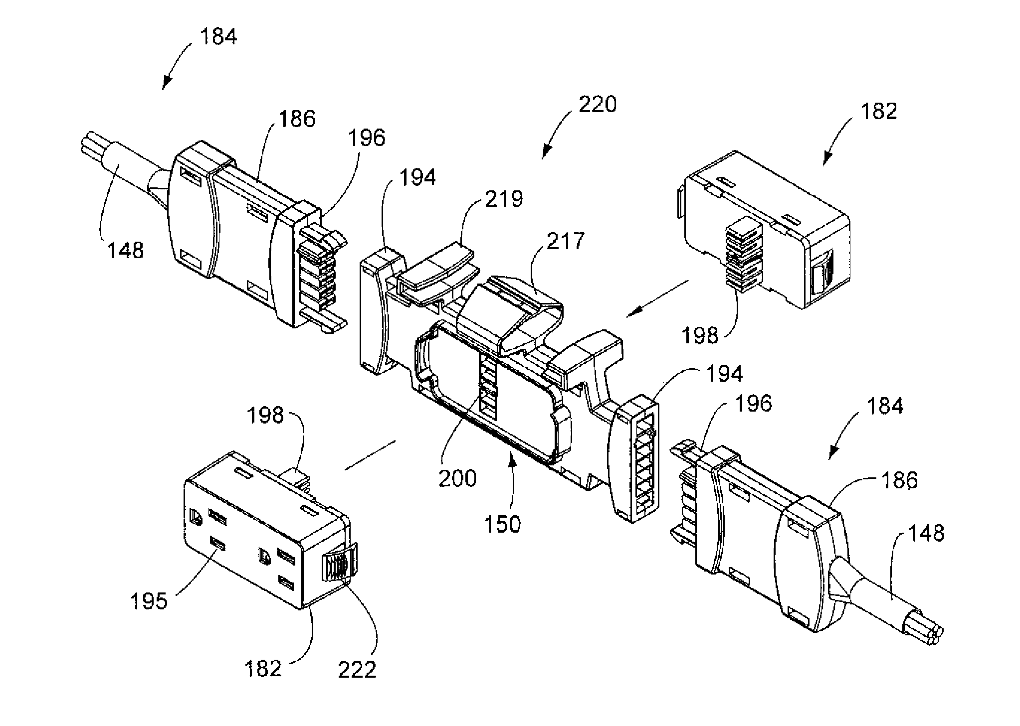
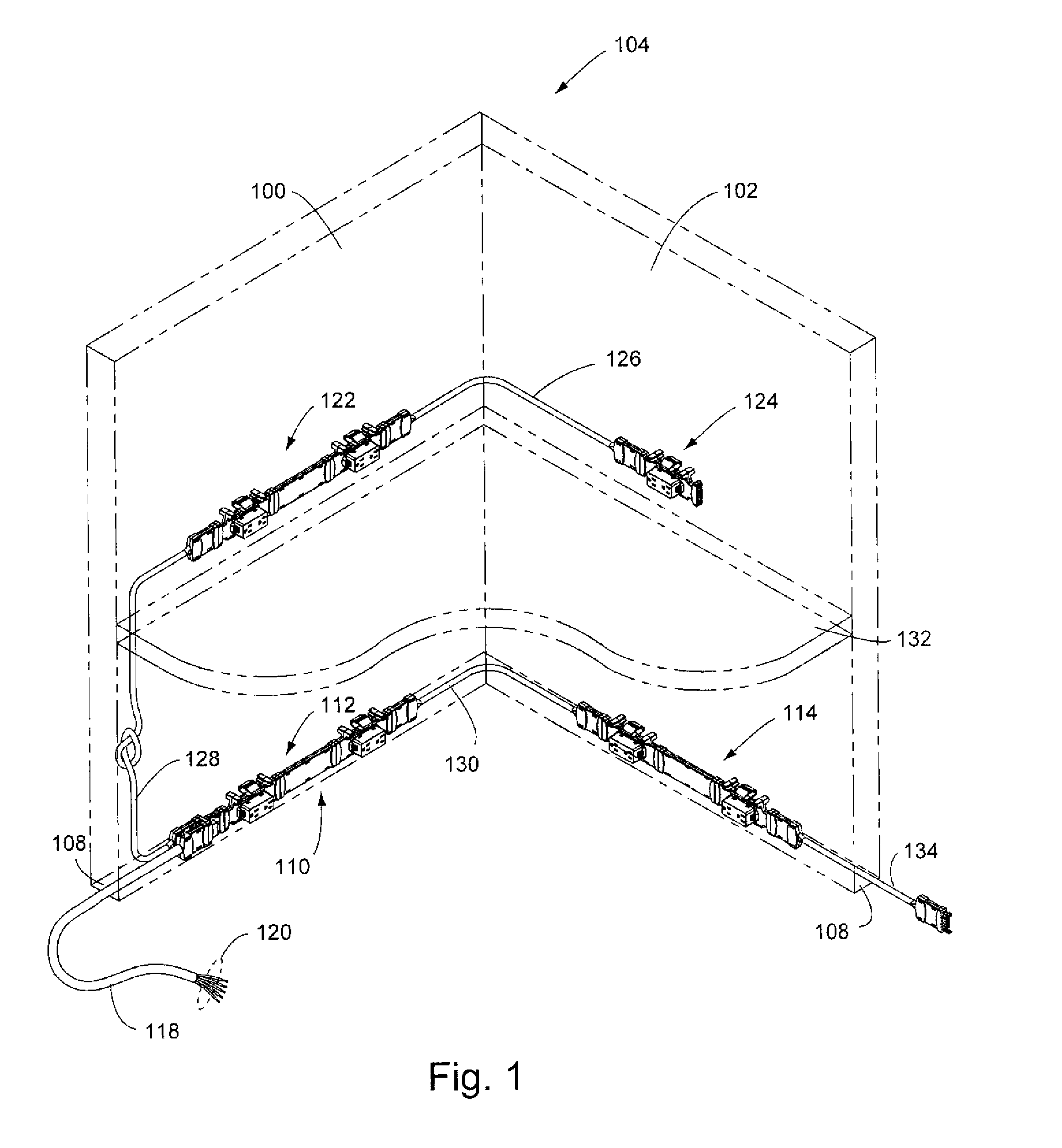
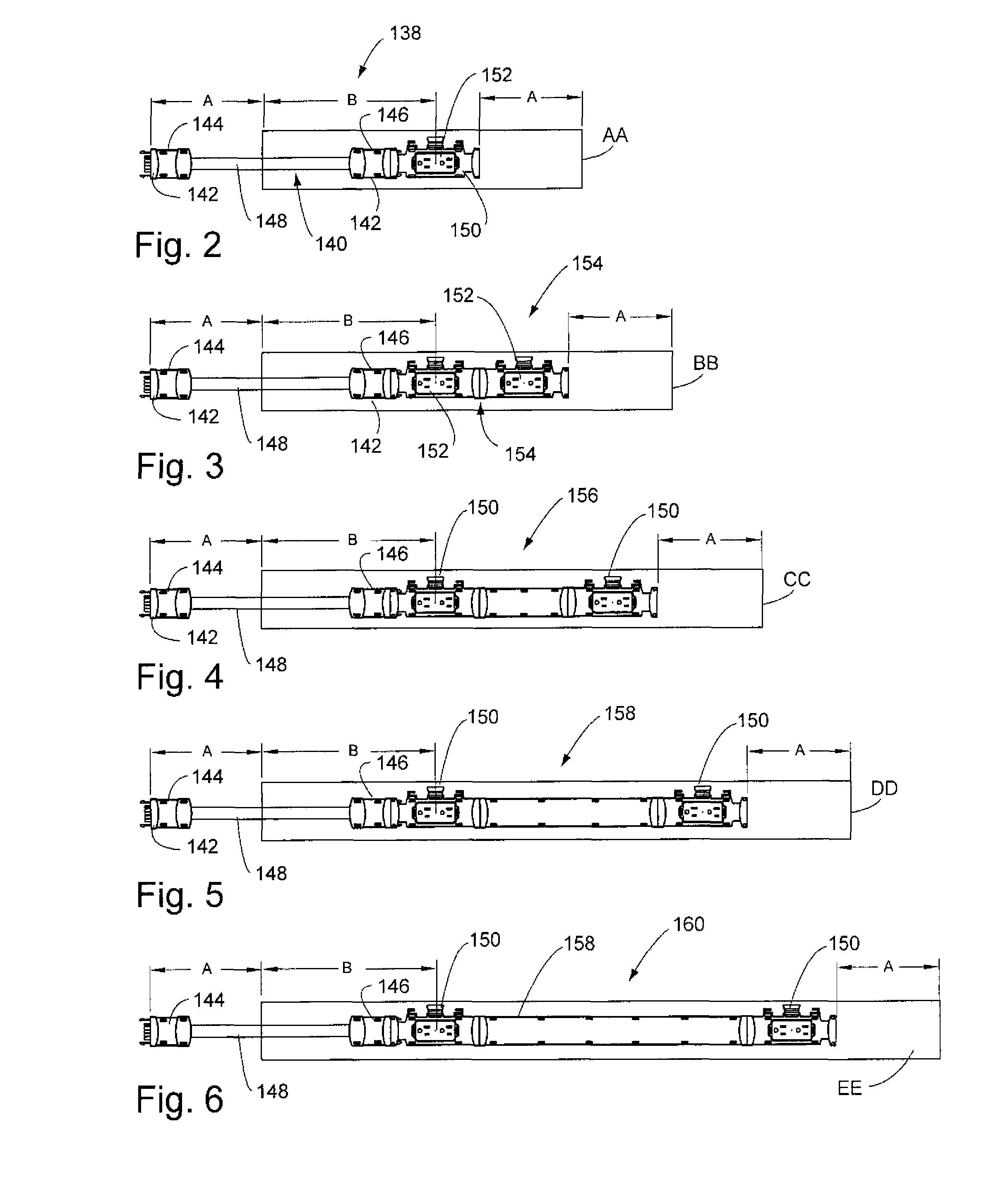
[0272]The principles of the invention are disclosed, by way of example, within modular electrical systems which provide for various configurations of receptacle configurations and the capability of providing five circuitry, for purposes of facilitating use within environments having raceway systems and work surfaces. In addition, the principles of the invention are directed to the modular power distribution assembly with multiple circuits. These inventive principles will be described with respect to systems illustrated in FIGS. 1-231. First, some general concepts associated with modular electrical systems in accordance with the invention will be described, and thereafter detailed descriptions are included with respect to the individual types of components which may be utilized in systems in accordance with the invention. Following this description, various types of configurations of interconnection of electrical components in accordance with the invention will be described.

[0273]To ...


PUM


Abstract

A modular power distribution system (110) comprises an incoming power cable (118) adapted to connect to jumper cable assemblies (140) having female end connectors (142) and jumper cables (148) connecting together the female end connectors. Junction blocks (150) are connectible to the jumper cable assemblies (140) and are adapted to provide for multiple circuits. Electrical receptacle blocks (152) are adapted to electrically connect to the junction blocks (150), and are configured so as to electrically connect to one of the multiple circuits.

Description

CROSS-REFERENCE TO RELATED APPLICATIONS[0001]This application is based upon and claims priority of U.S. Provisional Patent Application Ser. No. 61 / 186,882, filed Jun. 14, 2009.STATEMENT REGARDING FEDERALLY SPONSORED RESEARCH OR DEVELOPMENT[0002]Not applicable.REFERENCE TO MICROFICHE APPENDIX[0003]Not applicable.BACKGROUND OF THE INVENTION[0004]1. Field of the Invention[0005]The invention relates to electrical power and communications distribution systems and, more particularly, to systems employing modular components with the capability of utilizing multiple circuit configurations, with arrangements for electrically interconnecting outlet receptacle blocks so as to provide for a selected one of a plurality of power supply circuits.[0006]2. Background Art[0007]Known interior wall systems typically employ pre-fabricated modular units. These units are often joined together in various configurations, so as to divide a workplace into smaller offices or work areas. Generally, such modular...

Claims


Application Information

Patent Timeline
Patent Type & Authority Patents(United States)
IPC IPC(8): H01R4/60
CPCH01R25/142H01R25/16H02G3/00H02G3/386H01R13/56H01R13/6275
Inventor BYRNE, NORMAN R.
Owner BYRNE NORMAN R
Learn More