Image pickup lens
a pickup lens and image technology, applied in the field of compact image pickup lenses, can solve the problems of insufficient chromatic aberration correction, inability to secure excellent performance, and the image pickup lens cannot cope with a larger number of pixels in the image sensor, so as to achieve favorable chromatic aberration of magnification, and favorable chromatic aberration of longitudinal chromatic aberration
- Summary
- Abstract
- Description
- Claims
- Application Information
AI Technical Summary
Benefits of technology
Problems solved by technology
Method used
Image

Examples
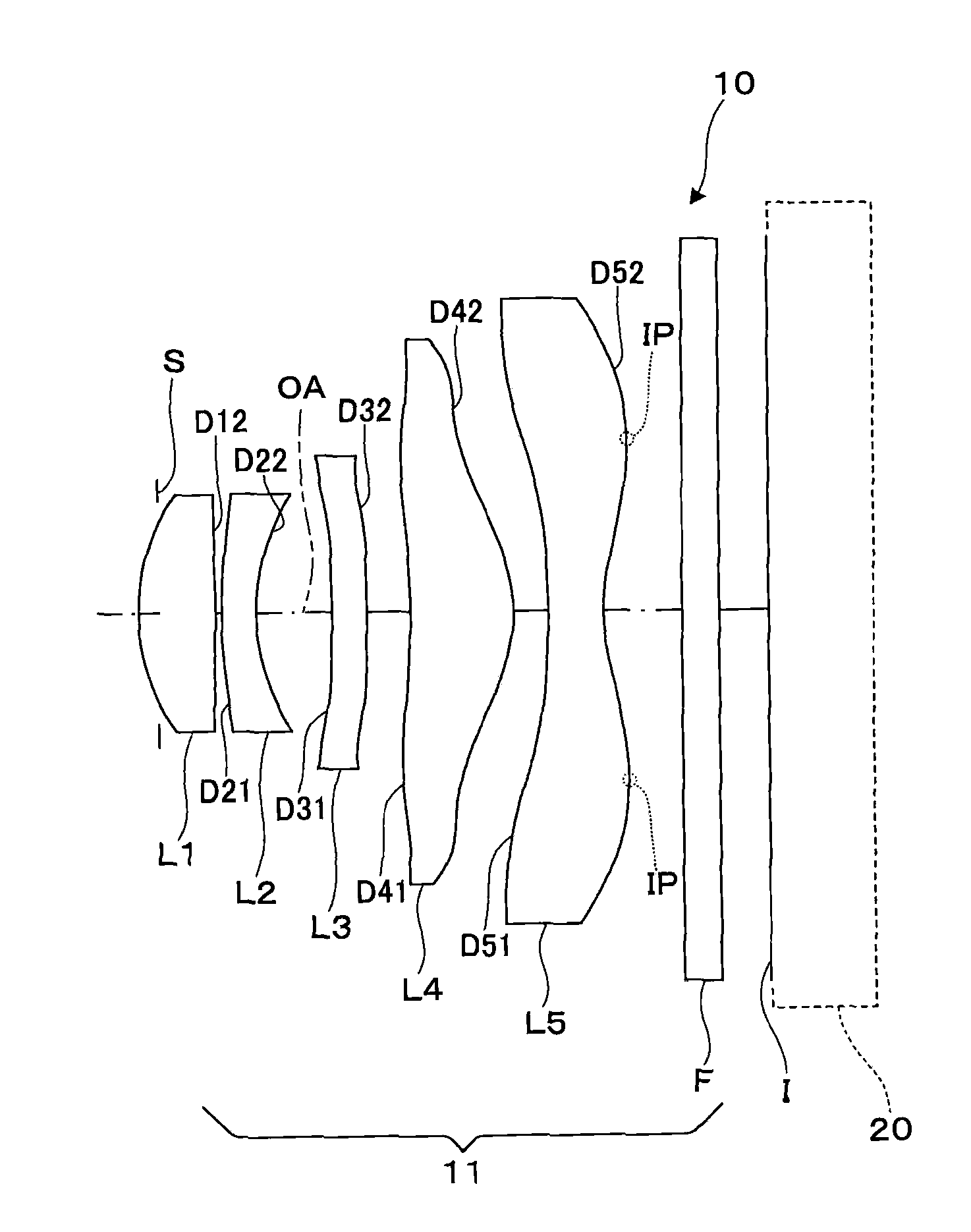
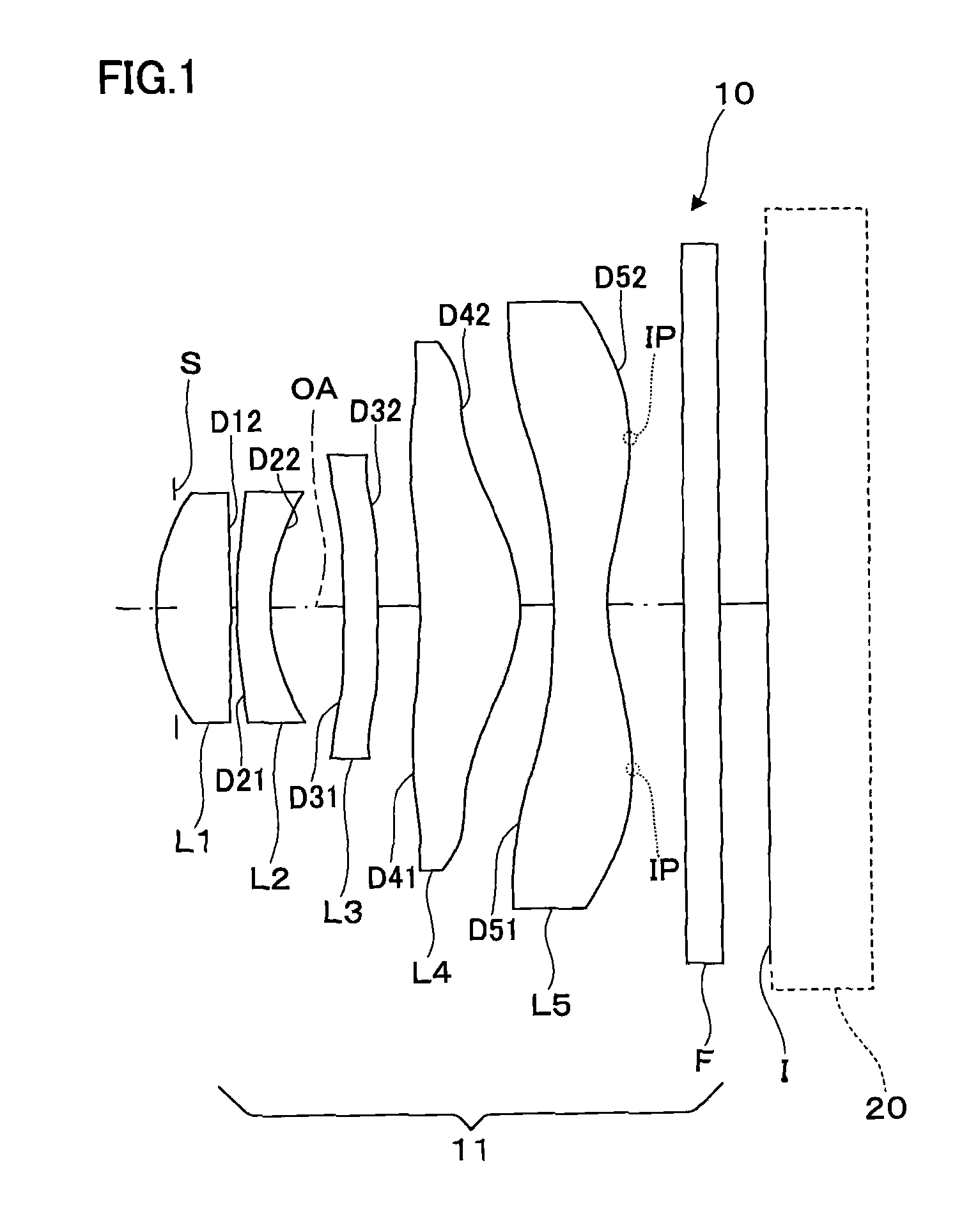
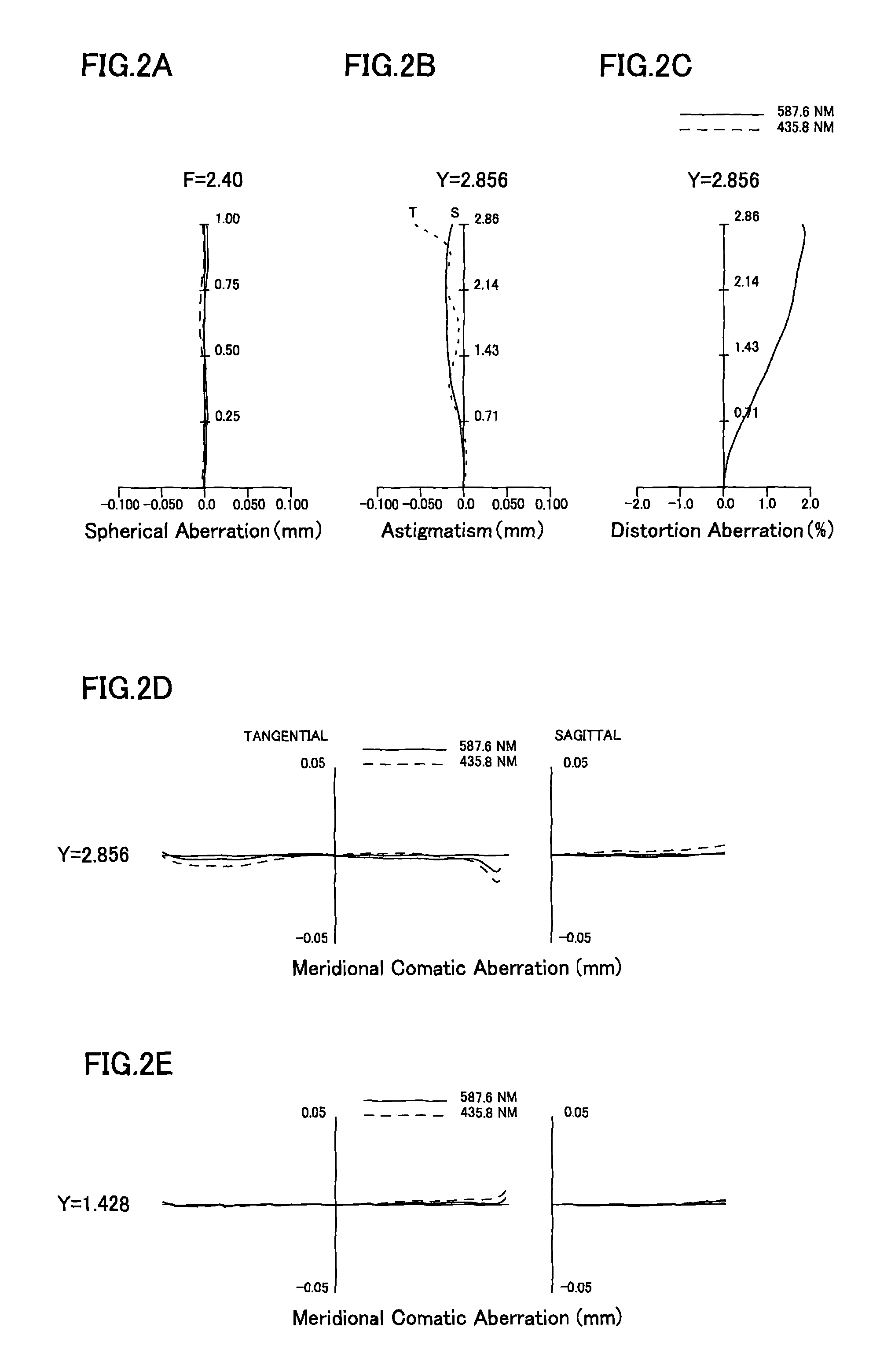
example 1
[0087]General specifications of the image pickup lens of Example 1 are as follows.
f=4.32 mm
fB=0.4 mm
F=2.4
2Y=5.712 mm
ENTP=0 mm
EXTP=−2.98 mm
H1=−1.21 mm
H2=−3.92 mm
[0088]Lens surface data of Example 1 is shown in Table 1 below.
[0089]
TABLE 1SER(mm)(Surface(EffectiveNo.)R(mm)D(mm)Ndνdradius) 1(stop)infinite−0.160.90 2*1.6990.631.5447056.20.95 3*−12.1450.050.95 4*3.7310.281.6347023.90.96 5*1.4830.620.95 6*111.6750.291.6347023.91.12 7*infinite0.361.26 8*−6.2380.841.5447056.22.00 9*−1.1740.282.2010*−8.3410.451.5305055.72.2611*1.4990.642.5312infinite0.301.5163064.13.0013infinite3.00Aspheric coefficients of lens surfaces of Example 1are as follows.Second surfaceK = 0.44504E−01, A4 = 0.40998E−02, A6 = 0.37944E−02,A8 = −0.50547E−02, A10 = 0.42441E−02Third surfaceK = 0.18502E+02, A4 = 0.28661E−01, A6 = 0.58087E−01,A8 = −0.10185E+00, A10 = 0.49818E−01Fourth surfaceK = −0.29604E+02, A4 = −0.59078E−01, A6 = 0.18979E+00,A8 = −0.25797E+00, A10 = 0.15802E+00, A12 = −0.34719E−01Fifth surfaceK = −0.54222...
example 2
[0094]General specifications of the image pickup lens of Example 2 are as follows.
f=5 mm
fB=0.8 mm
F=2.47
2Y=7.8 mm
ENTP=0 mm
EXTP=−5.04 mm
H1=0.72 mm
H2=−4.2 mm
[0095]Lens surface data of Example 2 is shown in Table 3 below.
[0096]
TABLE 3SER(mm)(Surface(EffectiveNo.)R(mm)D(mm)Ndνdradius) 1(Stop)infinite0.051.01 2*9.1010.671.5447056.21.03 3*−4.0630.341.22 4*5.3070.401.6320023.41.52 5*2.2530.501.67 6*5.5750.611.5447056.21.86 7*infinite0.721.92 8*−2.7101.121.5447056.22.14 9*−1.3380.052.2710*3.6280.991.5830030.02.8311*1.3210.833.4712infinite0.481.5163064.13.6913infinite3.79Aspheric coefficients of Example 2 are as follows.Second surfaceK = −0.30000E+02, A4 = −0.21046E−01, A6 = −0.59261E−02,A8 = −0.25609E−02, A10 = −0.31303E−02, A12 = 0.28389E−02,A14 = −0.93068E−03Third surfaceK = 0.76859E+01, A4 = 0.16319E−02, A6 = −0.58503E−02,A8 = 0.41599E−02, A10 = −0.14967E−02, A12 = −0.98328E−03,A14 = 0.11189E−02Fourth surfaceK = 0.29008E+01, A4 = −0.40187E−01, A6 = 0.22047E−01,A8 = −0.94282E−02, A10 = −0....
example 3
[0101]General specifications of the image pickup lens of Example 3 are as follows.
f=3.77 mm
fB=0.31 mm
F=2.22
2Y=5.744 mm
ENTP=0.45 mm
EXTP=−2.68 mm
H1=−0.54 mm
H2=−3.46 mm
[0102]Lens surface data of Example 3 is shown in Table 5 below.
[0103]
TABLE 5SER(mm)(Surface(EffectiveNo.)R(mm)D(mm)Ndνdradius) 1infinite0.001.24 2*2.0590.621.5447056.21.05 3*−8.8950.000.87 4(Stop)infinite0.130.78 5*5.4810.301.6320023.40.83 6*1.7770.380.91 7*7.2860.551.5447056.21.07 8*infinite0.461.26 9*−4.3820.741.5447056.21.4910*−0.9490.071.6811*11.4780.631.5447056.22.1612*0.9340.702.5313infinite0.151.5163064.12.7414infinite2.77Aspheric coefficients of Example 3 are as follows.Second surfaceK = −0.11904E+00, A4 = −0.54113E−02, A6 = −0.72751E−02,A8 = −0.10323E−03, A10 = −0.10448E−01, A12 = 0.80181E−02,A14 = −0.96657E−02Third surfaceK = −0.50000E+02, A4 = 0.23385E−01, A6 = −0.28146E−01,A8 = −0.62676E−02, A10 = −0.17296E−01, A12 = −0.90549E−02,A14 = 0.13679E−01Fifth surfaceK = 0.18031E+02, A4 = −0.45742E−01, A6 = 0.68627E−...
PUM
 Abstract
Description
Claims
Application Information
 - R&D
- Intellectual Property
- Life Sciences
- Materials
- Tech Scout
- Unparalleled Data Quality
- Higher Quality Content
- 60% Fewer Hallucinations
Browse by: Latest US Patents, China's latest patents, Technical Efficacy Thesaurus, Application Domain, Technology Topic, Popular Technical Reports.
© 2025 PatSnap. All rights reserved.Legal|Privacy policy|Modern Slavery Act Transparency Statement|Sitemap|About US| Contact US: help@patsnap.com