Magnetic control valve

a magnetic control valve and valve plug technology, applied in the direction of valve details, valve arrangement, valve operating means/releasing devices, etc., can solve the problems of non-smooth situation, rod body movement, non-smooth situation, etc., and achieve the effect of increasing the sealing effect between the valve plug and the valve and smooth draining water away

Active Publication Date: 2013-08-06
YUAN MEI CORP
View PDF17 Cites 8 Cited by
  • Summary
  • Abstract
  • Description
  • Claims
  • Application Information

AI Technical Summary

Benefits of technology

[0008]A primary objective of the present invention is to provide a magnetic control valve that has less parts than conventional structures and low manufacturing cost, smooth control motions of opening and closing valves, and light weight for volume without occupying spaces.
[0010]A rubber ring is combined with a metal plate, wherein the metal plate in the embodiment is encapsulated inside the rubber ring, and the metal plate can be made of a metal material capable of being attracted by magnetic force, and the metal plate has a central hole. A plurality of through holes is distributed to a periphery of the central hole. A valve, which is encapsulated in the central hole of the metal plate, is formed at the rubber ring. The glue body of the rubber ring is filled within each through hole to cascade the glue bodies covering the metal plate so that the metal plate is firmly combined with the rubber ring. In addition, a flexible loop blade is connected to a periphery of the rubber ring, and an external ring is connected to a periphery of the flexible loop blade. The periphery at a bottom of the rubber ring can completely seal the inlet end of the water outflow passage, and a bottom of the external ring can seal the outlet end of the water inflow passage. A convex ring is downwardly extended from an external edge at the bottom of the external ring. The convex ring can closely fit the inner concave slot of the circular seat. More than one communicating water passages are disposed to a region of the flexible loop blade.
[0013]The valve rod is fit inside the lower pipe body space and can be properly displaced and regulated. A bottom of the valve rod has a valve plug capable of completely sealing the valve of the rubber ring. The valve rod can be made of a magnetic material. In the embodiment, the valve rod comprises a magnetic element, a rubber sleeve pipe and a sealing cap for encapsulating the magnetic element. The valve plug of the valve rod is disposed at the external bottom of the sealing end of the rubber sleeve pipe. The opening of the valve plug is sealed by the external cover. Accordingly, the magnetic element may not be eroded by water.
[0015]Reversely, when the electromagnetic coil controlled by the switch generates a magnetic file mutually attracted with a magnetic pole at an end of the valve rod and a magnetic force of the magnetic field is larger than the magnetic force of the valve rod attracted to the metal plate, the valve rod comes off the metal plate to instantly move toward a reverse direction to allow an end of the valve rod attracting the magnetic element so that the valve plug of the valve rod completely comes off the valve of the rubber ring to allow the valve shows an opening state. Accordingly, water flow originally staying in the lower containing chamber is introduced into the inlet end of the water outflow passage via the valve of the rubber ring, thereby smoothly draining water away.

Problems solved by technology

However, the defects commonly existing in the foregoing prior arts are that when the valve is opened, the moved rod body moves toward a direction that is opposite to the pushing of the flexible element.
A reverse damper generated by the flexible element that is compressed may cause shift phenomenon at the moving path for the rod body, resulting in non-smooth situation.
Moreover, the rod bodies utilized in the prior arts did not have magnetic function, and parts of disposing the valve are purely made of rubber.
None of any company can develop other innovate design in the present time.
Further, the foregoing published application and patents may also require many parts assembled to the whole structures to have drawbacks of higher manufacturing costs and labor costs at the installation operation.
Consequently, the size of the magnetic control valve is extremely big and may not be reduced to achieve light weight and small sizes.

Method used


Image

  • Magnetic control valve
  • Magnetic control valve
  • Magnetic control valve

Examples


Embodiment Construction

[0025]Other features and advantages of the present invention will become apparent from the following description of the invention which refers to the accompanying drawings.

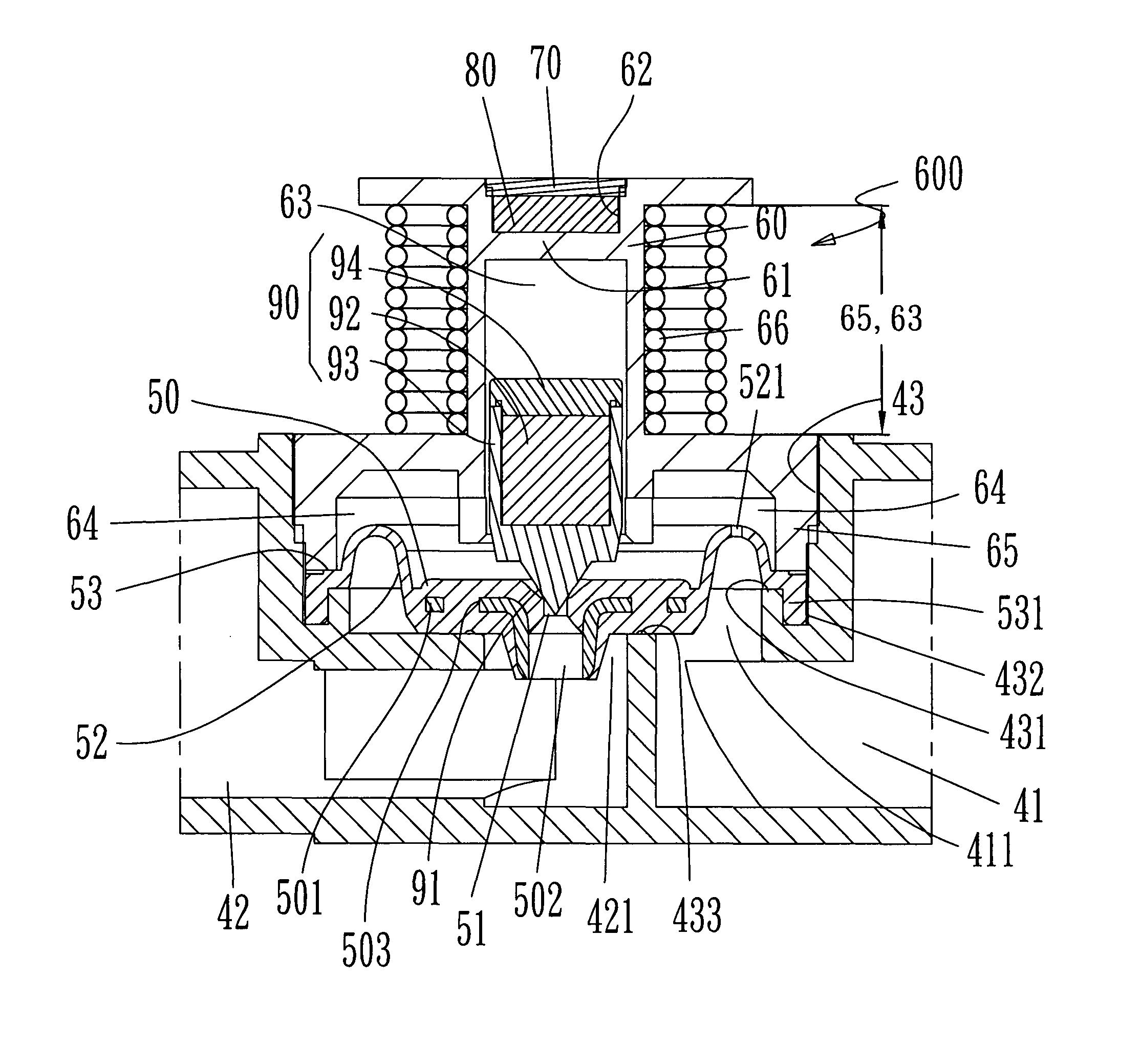
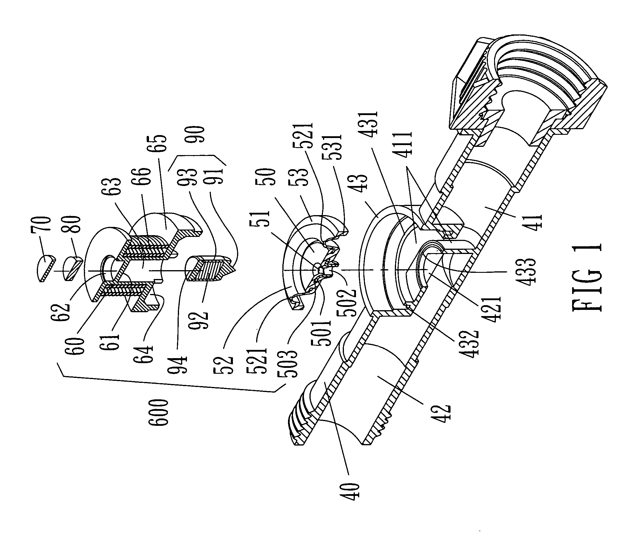
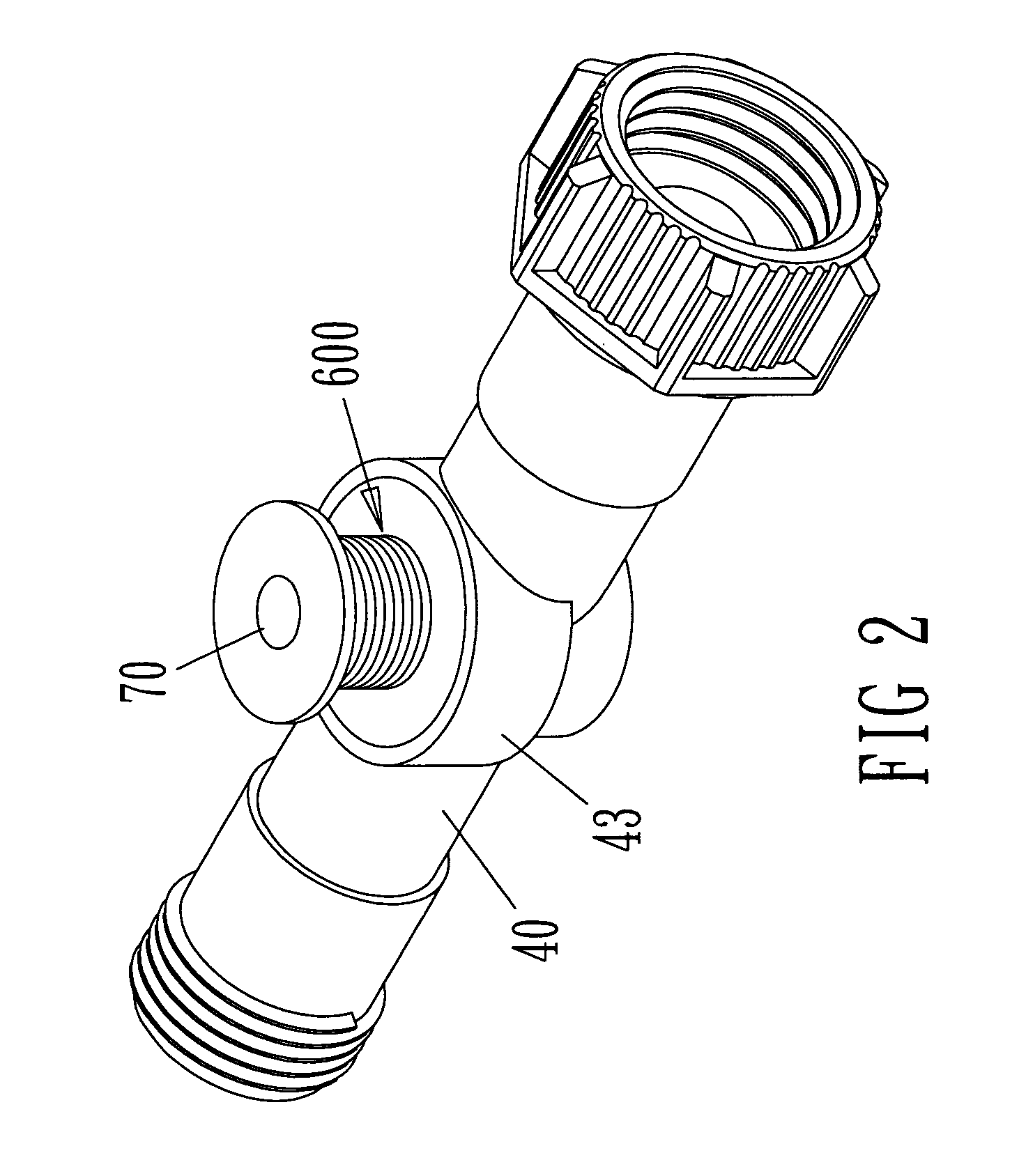
[0026]Referring FIG. 1 to FIG. 7 for a magnetic control valve in accordance with a preferred embodiment of the present invention is depicted. The magnetic control valve comprises a connection pipe 40. The connection pipe 40 has a water inflow passage 41 and a water outflow passage 42, a circular seat 43 disposed to an engaging place between an outlet end 411 of the water inflow passage 41 and an inlet end 421 of the water outflow passage 42, wherein the circular seat has an outward opening. A bottom of the circular seat 43 has an external baffle ring 431 formed at the outlet end 411 of the water inflow passage 41, and an inner concave slot 432 is disposed to an upper end surface of the external baffle ring 431. An inner baffle ring 433 is formed with respect to the inlet end 421 of the water outflow passage 42, an...


PUM


Abstract

A magnetic control valve is to block an outlet end of a water inflow passage and an inlet end of a water outflow passage of a connection pipe by using a rubber ring. A valve of the rubber ring is opened or closed by a magnetic control switch. The magnetic control switch mainly takes a valve rod carrying permanent magnetic force that completely controls direction of electromagnetic pole as a power source for moving. When a valve plug at an end of the valve rod seals the valve, a metal plate capable of being sucked by magnetic force is combined with the rubber ring to allow both to generate magnetic sucking effect, thereby firmly closing.

Description

FIELD OF THE INVENTION[0001]The present invention relates to a facility for controlling the turn-on state or the turn-off state of water flow, and more particularly to a technical innovation field of controlling the turn-on state or the turn-off state of water flow by applying a magnetic control valve.BACKGROUND OF THE INVENTION[0002]According to prior arts that are similar to a technique shown in the case, including U.S. published applications 20050184261, 20100019179, 20090224191, 20080216896, U.S. Pat. Nos. 7,296,593, 6,691,937, 6,688,577, 6,675,826, 6,619,612, 5,497,135, 6,073,904, 6,076,550, 7,637,475, 5,599,003, 5,503,362, 5,269,333, 5,145,145, 4,948,090, 4,934,651, 6,457,697, 5,738,138, 5,676,342, 7,703,740, 5,565,747, and 5,622,351, the technique features shown in the foregoing prior arts utilize a valve to partition pipes and water passages. The valve is controlled by a valve rod to show an opening or closing state. The valve rod is disposed to an end of a rod body. Another...

Claims


Application Information

Patent Timeline
Patent Type & Authority Patents(United States)
IPC IPC(8): F16K31/02
CPCF16K31/404
Inventor CHENG, CHI-HAN
Owner YUAN MEI CORP
Why Eureka
Try Eureka