Method and device for purging gas production furnace

a gas production furnace and gas technology, applied in the direction of furnaces, combustion types, borehole/well accessories, etc., can solve the problems of fast and furious combustion, substantial increase in purging cost, etc., and achieve the effect of reducing the used amount of inert gas, substantial reduction of purging cost and purging tim

Active Publication Date: 2013-08-06
IHI CORP
View PDF14 Cites 0 Cited by
  • Summary
  • Abstract
  • Description
  • Claims
  • Application Information

AI Technical Summary

Benefits of technology

[0022]According to a method and a device for purging a gas production furnace of the invention, upon shutdown or startup of the gas production furnace, the gas production furnace is supplied with an inert gas from below for purging of a produced gas in the bed material with the inert gas while at the same time a freeboard section above the bed material is supplied with steam for purging of a produced gas in the freeboard section; thus, the inert gas supplied will suffice in an amount of purging only the bed material, resulting in substantial reduction in the used amount of the inert gas; the freeboard section may be purged with inexpensive steam, resulting in substantial reduction in cost for purging and in purging time.
[0023]When the freeboard section is supplied with steam for purging while at the same time the bed material is purged with the inert gas, the steam for the freeboard section can be prevented from contacting the raw material of the bed material; as a result, a problem that the raw material of the bed material is gasified to newly produce a produced gas can be prevented.
[0024]Steam with lower temperature and with lower pressure will suffice as steam for purging the freeboard section, so that residual heat steam produced by residual heat upon shutdown of the gas production furnace may be used for purging of the freeboard section.

Problems solved by technology

When the circulating fluidized bed furnace 3 in operation is to be shut down, there is also a fear that admixture of air into the gasification facility filled with combustive produced gas may bring about fast and furious combustion.
Such requirement of inert gas 23 in large quantity brings about a problem that a large-sized inert gas producer is required, resulting in substantial increase in cost for purging.

Method used


Image

  • Method and device for purging gas production furnace
  • Method and device for purging gas production furnace
  • Method and device for purging gas production furnace

Examples


Embodiment Construction

[0041]An embodiment of the invention will be described in conjunction with the attached drawings.

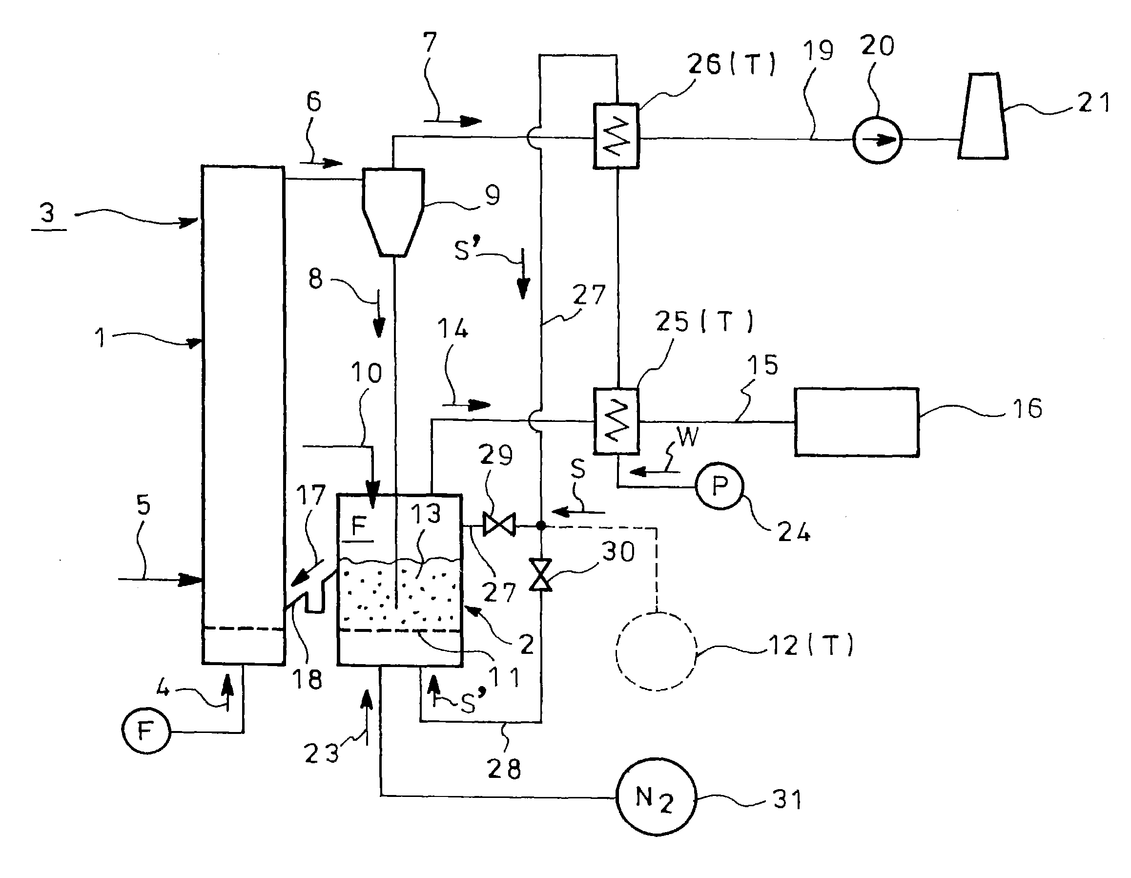
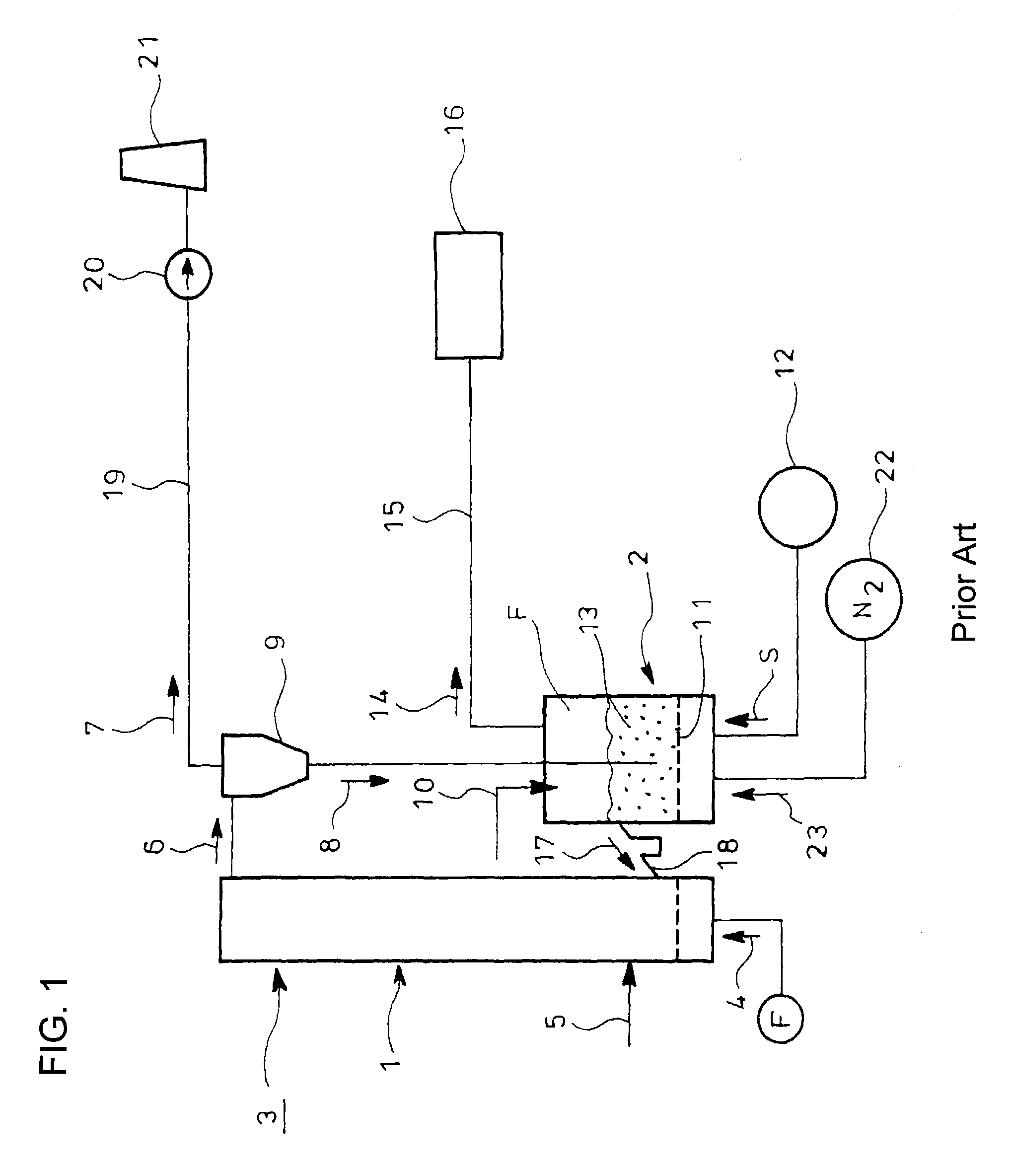
[0042]The invention is disclosed in terms of an example of a method for purging a gas production furnace comprising a fluidized bed formed and a freeboard section above a bed material so as to produce a produced gas by a reaction of raw material with a gasifying agent and take out the produced gas through the freeboard section. This purging method is therefore applicable to a wide variety of gas production furnaces, e.g., any gasification furnaces with a bed material such as a fluidized bed gasification furnace other than the circulating fluidized bed furnace 3 shown in FIG. 1 or a moving or fixed bed gasification furnace, or a coke oven for production of a produced gas through a fixed bed.

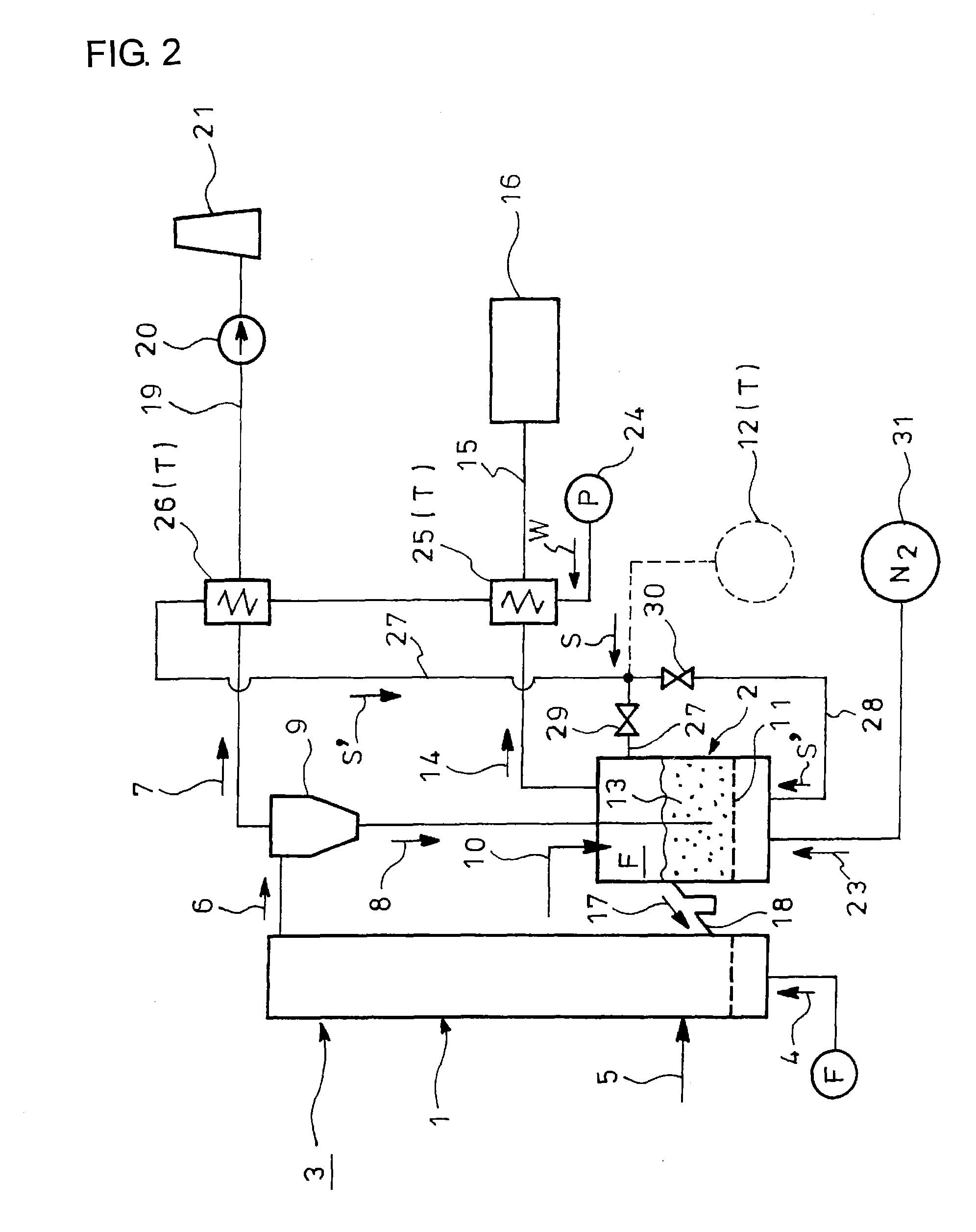
[0043]FIG. 2 shows an embodiment of the invention applied to a circulating fluidized bed furnace 3 having a combustion furnace 1 and a fluidized bed gasification furnace 2 (gas production furnace) just...


PUM


Abstract

A fluidized bed gasification furnace has a fluidized bed formed and a freeboard section F above a bed material so as to produce a produced gas by a reaction of raw material with a gasifying agent and take out the produced gas through the freeboard section. Upon shutdown of the furnace, inert gas is fed from below to the furnace for purging of gas in the fluidized bed with inert gas while steam is supplied to a freeboard section above the fluidized bed to purge a gas in the freeboard section with steam.

Description

TECHNICAL FIELD[0001]The present invention relates to a method and a device for purging a gas production furnace capable of safely and inexpensively purging the gas production furnace within a short time, the gas production furnace comprising a fluidized bed formed and a freeboard section above a bed material so as to produce a produced gas by a reaction of raw material with a gasifying agent and take out the produced gas through the freeboard section.BACKGROUND ART[0002]FIG. 1 shows an example of a circulating fluidized bed furnace 3 comprising a combustion furnace 1 and a fluidized bed gasification furnace 2 for production of a produced gas. Prior art literature for such circulating fluidized bed furnace is, for example, Patent Literature 1.[0003]In the combustion furnace 1 constituting the circulating fluidized bed furnace 3 of FIG. 1, air or oxygen 4 is supplied from below, and at least either startup fuel 5 or char referred to hereinafter is supplied to a lower side portion of ...

Claims


Application Information

Patent Timeline
Patent Type & Authority Patents(United States)
IPC IPC(8): F27B15/10
CPCF23G5/0276F23G5/30C10J3/463C10J3/728F23G2201/304F23G2201/40F23G2203/501F23G2203/503F23G2208/10C10J2300/0976C10J2300/0993C10J2300/1637C10J2300/1807
Inventor KATAGIRI, TOMOYUKINUKUMI, HISANORIKONDO, KENICHIRO
Owner IHI CORP
Why Eureka
Try Eureka