Method for the operation of a transmission device of a vehicle drive train

a transmission device and drive train technology, applied in mechanical equipment, transportation and packaging, gearing, etc., can solve the problems of unfavorable control of the shift element, and inability to determine the moment only in advance with difficulty, and achieve the effect of simple and inexpensiv

Active Publication Date: 2013-08-06
ZF FRIEDRICHSHAFEN AG
View PDF17 Cites 32 Cited by
  • Summary
  • Abstract
  • Description
  • Claims
  • Application Information

AI Technical Summary

Benefits of technology

[0008]Accordingly, the purpose of the present invention is to provide a method for operating a transmission device of a vehicle drive train, by means of which an intermediate operating condition of a shift element, or tooth-on-tooth position of an interlocking shift element, can be eliminated in a simple and inexpensive manner without exact knowledge of the current operating condition of the interlocking shift element.
[0010]According to the invention, to produce a speed difference between the shift element halves of the interlocking shift element, the transmission capacity of at least one frictional shift element is increased.
[0011]In this way the intermediate operating condition of an interlocking shift element, which for example corresponds to a tooth-on-tooth position of the interlocking shift element, can be resolved without exact knowledge of the current operating condition of the interlocking shift element, in a purely functional, simple and inexpensive manner by increasing the transmission capacity of at least one frictional shift element already present in the transmission device.
[0012]In addition, by means of the procedure according to the invention an interlocking shift element can be changed out of intermediate or undefined operating conditions, which can occur for example in a transmission device after the first operation of a drive machine of the vehicle drive train begins and during which there is between the shift element halves of an interlocking shift element too high a rotation speed difference to enable the interlock to be formed, into an operating condition necessary for a closing process of the interlocking shift element. This means that the speed difference between the shift element halves of the interlocking shift element can be adjusted to a value necessary for enabling the production of the interlock in the area of the interlocking shift element, by increasing the transmission capacity of the frictional shift element.
[0013]With the procedure proposed according to the invention, in contrast to the procedure known from the prior art there is no need for exact knowledge of the operating point of an interlocking shift element in the event of an intermediate operating condition, since during the method according to the invention the operating condition of the interlocking shift element is not changed directly by varying the actuation of the interlocking shift element, but instead by increasing the transmission capacity of at least one frictional shift element of the transmission device. This increase of the transmission capacity of the frictional shift element brings about in the area of the interlocking shift element a rotational speed difference between the shift element halves of the interlocking shift element, such that the interlocking shift element can be closed.
[0014]In an advantageous variant of the method according to the invention, to produce the speed difference the transmission capacity of the frictional shift element is increased while at least one further shift element is closed, such that by virtue of the frictional shift element and the further frictional shift element in the closed condition a gear ratio of the transmission device can be obtained.

Problems solved by technology

In automatic transmissions known from practice which, besides frictional shift elements, also comprise interlocking shift elements for obtaining various gear ratios, in unfavorable operating conditions the possibility exists that during a change in the operating condition of the automatic transmission or during a gearshift an interlocking shift element cannot be changed to the desired extent from an open operating condition, during which the shift element halves of the interlocking shift element are out of engagement, to a closed operating condition in which the shift element halves are connected rotationally fixed with one another in an interlocked manner.
During such an intermediate operating condition of an interlocking shift element, in the area of the interlocking shift element there is a frictional connection between its shift element halves, which is suddenly broken only when a certain load point is exceeded, so the interlock is produced in the area of the shift element, undesirably, at a moment which can only be determined in advance with difficulty.

Method used


Image

  • Method for the operation of a transmission device of a vehicle drive train
  • Method for the operation of a transmission device of a vehicle drive train
  • Method for the operation of a transmission device of a vehicle drive train

Examples


Embodiment Construction

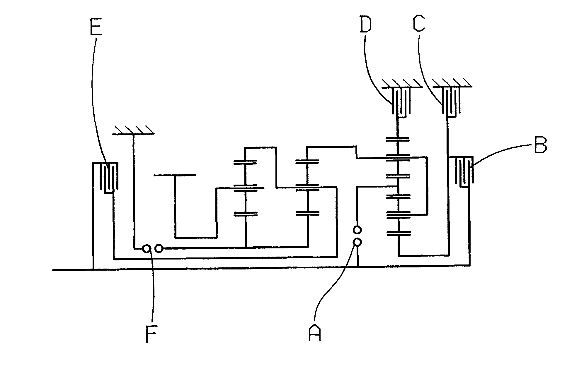
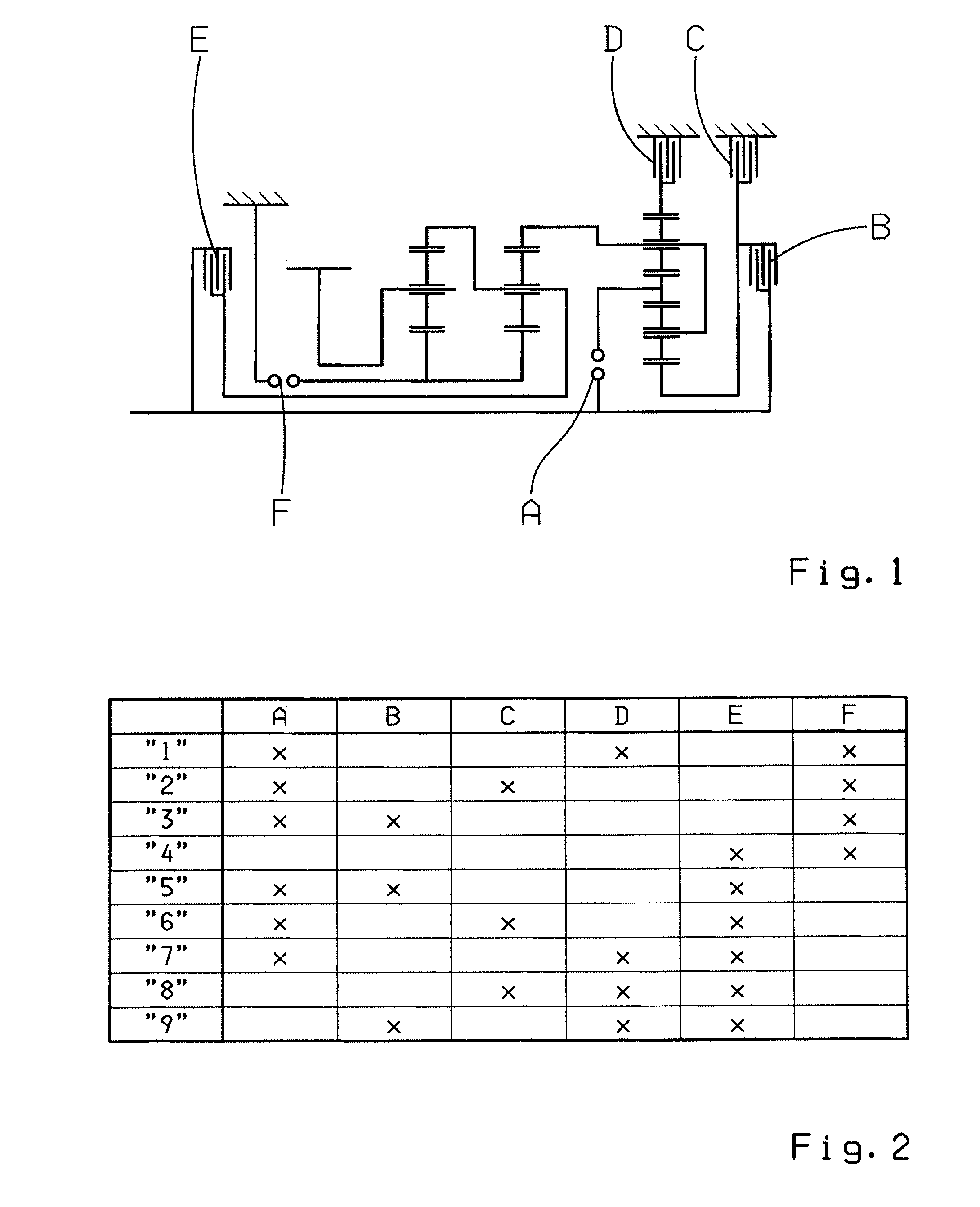
[0023]FIG. 1 shows a gear layout of a transmission device 1 having two interlocking shift elements A and F and four frictional shift elements B, C, D and E. By means of the shift elements A to F various shafts of the transmission device 1, in this case designed as a planetary transmission, can be connected to one another in the manner required in each case in order to obtain various gear ratios “1” to “9”.

[0024]To obtain the gear ratios “1” to “9” in each case a plurality of the shift elements A to F have to be engaged in the force flow of the transmission device 1, the shift elements A to F which are engaged in the force flow in each case being indicated in FIG. 2 with an X, while the other shift elements are in each case in the open operating condition. For example, to obtain the first gear “1” the shift elements A, D and F have to be engaged in the force flow of the transmission device 1, while at the same time the shift elements B, C and E are in the fully open operating conditi...


PUM


Abstract

A method of operating a transmission of a vehicle drive train with at least one drive machine. The transmission is formed with at least one interlocking shift element and a plurality of frictional shift elements in order to obtain various gear ratios. During an engaging process of the interlocking shift element, starting from a disengaged operating condition, in which halves of the interlocking shift element are out of engagement, to an engaged operating condition, in which the shift element halves are interlocked in a rotationally fixed manner, when interlock between the shift element halves is obstructed, a rotational speed difference is produced at least temporarily between the shift element halves, at which the interlock in the area of the interlocking shift element can be engaged. To produce the speed difference between the shift element halves, the transmission capacity of at least one frictional shift element is increased.

Description

[0001]This application is a National Stage completion of PCT / EP2010 / 050342 filed Jan. 13, 2010, which claims priority from German patent application serial no. 10 2009 000 254.5 filed Jan. 15, 2009.FIELD OF THE INVENTION[0002]The invention concerns a method for operating a transmission device of a vehicle drive train.BACKGROUND OF THE INVENTION[0003]In automatic transmissions known from practice which, besides frictional shift elements, also comprise interlocking shift elements for obtaining various gear ratios, in unfavorable operating conditions the possibility exists that during a change in the operating condition of the automatic transmission or during a gearshift an interlocking shift element cannot be changed to the desired extent from an open operating condition, during which the shift element halves of the interlocking shift element are out of engagement, to a closed operating condition in which the shift element halves are connected rotationally fixed with one another in an...

Claims


Application Information

Patent Timeline
Patent Type & Authority Patents(United States)
IPC IPC(8): F16H61/00F16H3/44
CPCF16H61/0403F16H61/0437F16H61/686F16H2061/0407Y10T477/69383F16H2200/2064F16H2061/047F16H2200/2094F16H2061/0474B60W30/00B60W30/18F16H3/44F16H61/00F16H61/04
Inventor ARNOLD, JORGSTEINHAUSER, KLAUSHERBETH, VALENTINEPOPP, CHRISTIAN
Owner ZF FRIEDRICHSHAFEN AG
Why Eureka
Try Eureka