Inner focus lens, interchangeable lens apparatus and camera system

a technology of interchangeable lenses and focus lenses, which is applied in the field of inner focus lenses, interchangeable lens apparatuses, and camera systems, can solve the problems of inability to achieve the high-speed focusing demand of recent years and increase the movement of the positive lens unit, and achieve the effect of large apertur

Active Publication Date: 2013-08-06
PANASONIC CORP
View PDF3 Cites 10 Cited by
  • Summary
  • Abstract
  • Description
  • Claims
  • Application Information

AI Technical Summary

Benefits of technology

[0014]the second lens unit is moved along an optical axis so that focusing from an infinite-distance object side to a short-distance object side is achieved,
[0030]the second lens unit is moved along an optical axis so that focusing from an infinite-distance object side to a short-distance object side is achieved,
[0046]the second lens unit is moved along an optical axis so that focusing from an infinite-distance object side to a short-distance object side is achieved,
[0054]The present invention provides: an inner focus lens in which the construction is realized by a small number of lens elements and yet various kinds of aberrations are compensated satisfactorily and in which the amount of movement of a focusing lens unit at the time of focusing is small and the focusing lens unit has a light weight and hence, although a large aperture is implemented, high-speed focusing is achieved; and an interchangeable lens apparatus and a camera system employing this inner focus lens.

Problems solved by technology

This causes an increase in the amount of movement of the positive lens unit at the time of focusing, and hence high-speed focusing demanded in recent years is not realized.

Method used


Image

  • Inner focus lens, interchangeable lens apparatus and camera system
  • Inner focus lens, interchangeable lens apparatus and camera system
  • Inner focus lens, interchangeable lens apparatus and camera system

Examples


embodiments 1 to 6

[0113](Embodiments 1 to 6)

[0114]Detailed embodiments for the inner focus lens according to the present invention are described below with reference to the drawings.

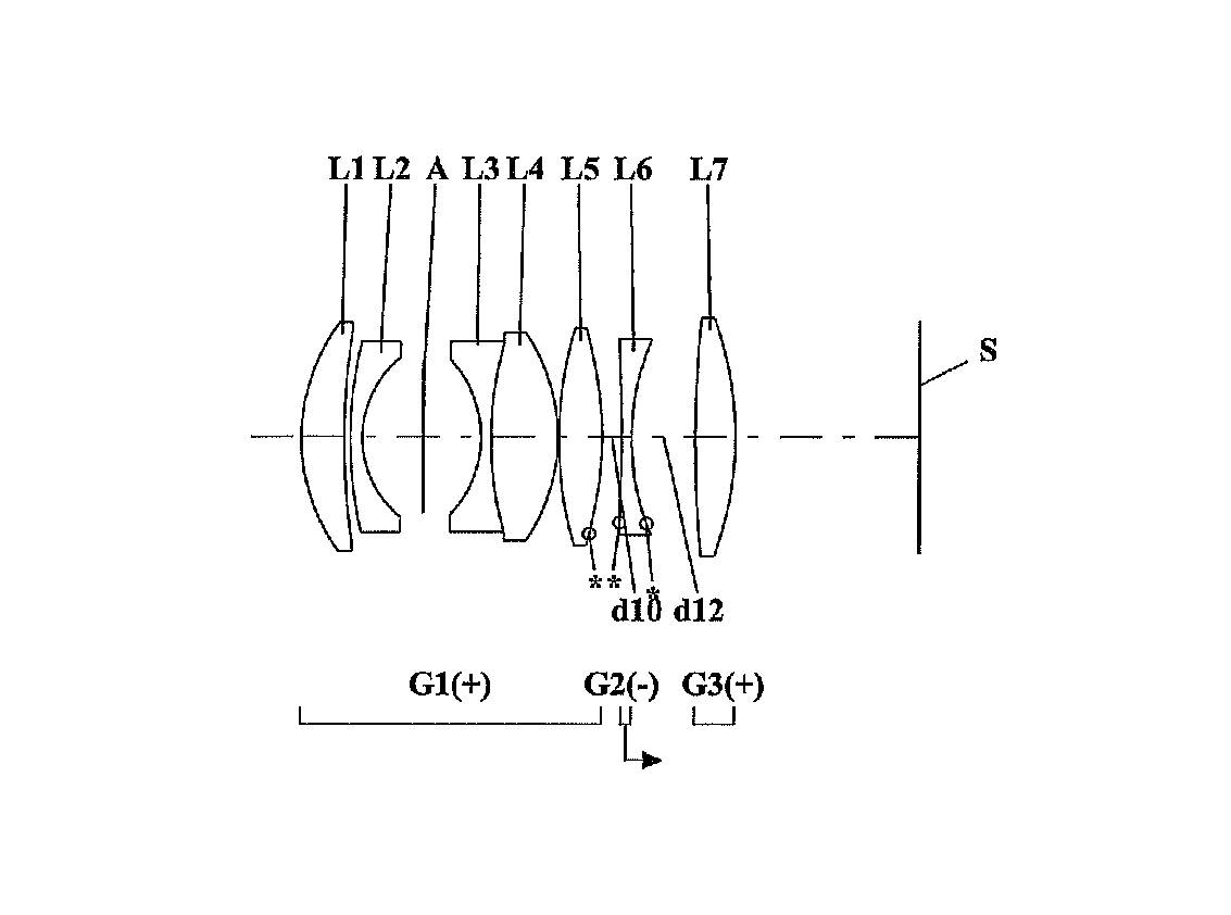
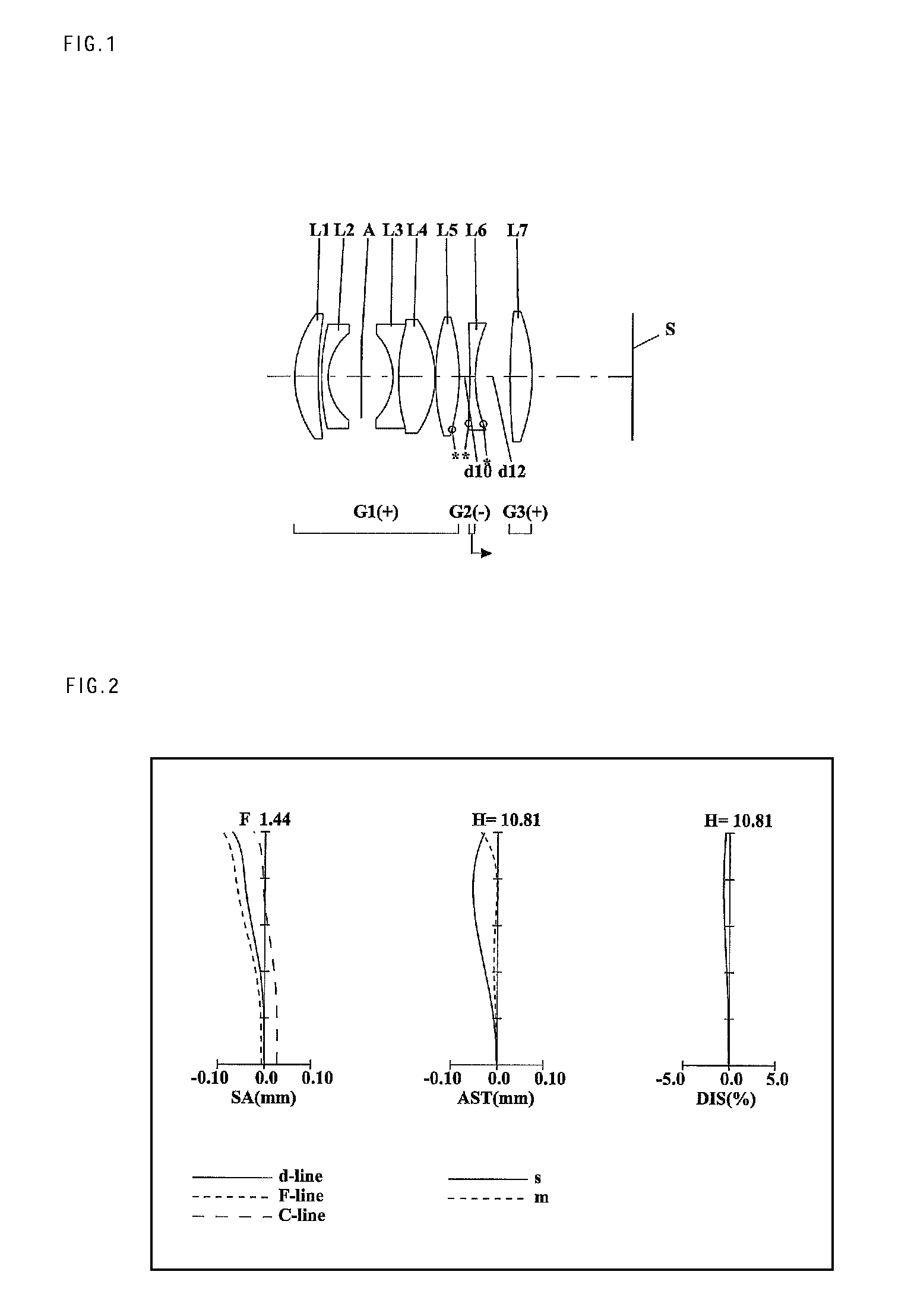
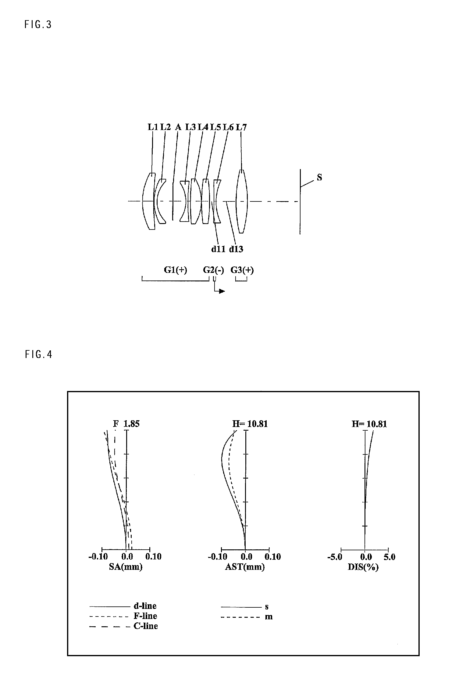
[0115]In each Fig., an asterisk “*” imparted to a particular surface indicates that the surface is aspheric. Symbol (+) or (−) imparted to the symbol of each lens unit corresponds to the sign of the optical power of each lens unit. An arrow imparted to each lens unit indicates the moving direction at the time of focusing from an infinite-distance object side to a short-distance object side. Further, a straight line located on the most right-hand side indicates the position of an image surface S.

embodiment 1

[0116]FIG. 1 is a lens arrangement diagram showing an infinity in-focus condition of the inner focus lens according to

[0117]The inner focus lens according to Embodiment 1, in order from an object side to an image side, comprises a first lens unit G1 having positive optical power, a second lens unit G2 having negative optical power, and a third lens unit G3 having positive optical power. In the inner focus lens according to Embodiment 1, the conditions (1) to (6) are satisfied.

[0118]The first lens unit G1, in order from the object side to the image side, comprises: a positive meniscus first lens element L1 with the convex surface facing the object side; a negative meniscus second lens element L2 with the stronger-curvature concave surface facing the image side; an aperture diaphragm A; a cemented lens element constructed from a bi-concave third lens element L3 with the stronger-curvature concave surface facing the object side and a bi-convex fourth lens element L4; and a bi-convex fi...

embodiment 2

[0121]FIG. 3 is a lens arrangement diagram showing an infinity in-focus condition of the inner focus lens according to

[0122]The inner focus lens according to Embodiment 2, in order from an object side to an image side, comprises a first lens unit G1 having positive optical power, a second lens unit G2 having negative optical power, and a third lens unit G3 having positive optical power. In the inner focus lens according to Embodiment 2, the conditions (1) to (6) are satisfied.

[0123]The first lens unit G1, in order from the object side to the image side, comprises: a positive meniscus first lens element L1 with the convex surface facing the object side; a negative meniscus second lens element L2 with the stronger-curvature concave surface facing the image side; an aperture diaphragm A; a bi-concave third lens element L3 with the stronger-curvature concave surface facing the object side; a bi-convex fourth lens element L4; and a bi-convex fifth lens element L5. In the first lens unit ...


PUM


Abstract

An inner focus lens, in order from an object side to an image side, comprising: a first lens unit having positive optical power; a second lens unit having negative optical power; and a third lens unit having positive optical power, wherein the second lens unit is moved along an optical axis so that focusing from an infinite-distance object side to a short-distance object side is achieved, the first lens unit includes a bi-convex air lens, and the following conditions: 0.65<|f2 / f|<5.00 and 0.5<f23 / f1<9.0 (f2: a focal length of the second lens unit, f and f23: a focal length of the entire system and a composite focal length of the second and third lens units in an infinity in-focus condition, f1: a focal length of the first lens unit) are satisfied; an interchangeable lens apparatus; and a camera system are provided.

Description

CROSS-REFERENCE TO RELATED APPLICATION[0001]This application is based on application No. 2011-085154 filed in Japan on Apr. 7, 2011 and application No. 2012-040218 filed in Japan on Feb. 27, 2012, the contents of which are hereby incorporated by reference.BACKGROUND OF THE INVENTION[0002]1. Field of the Invention[0003]The present invention relates to inner focus lenses, interchangeable lens apparatuses, and camera systems. Specifically, the present invention relates to: inner focus lenses suitable for an interchangeable lens apparatus attachable to a digital single-lens reflex camera or a single-lens reflex camera using silver salt films, a digital still camera, a camcorder, and the like; and interchangeable lens apparatuses and camera systems employing these inner focus lenses.[0004]2. Description of the Background Art[0005]In association with increases in the number of pixels of solid-state image sensors in recent years, imaging optical systems employed for them are requested to h...

Claims


Application Information

Patent Timeline
Patent Type & Authority Patents(United States)
IPC IPC(8): G02B15/14G02B7/02
CPCG02B9/14G02B13/02
Inventor IMAOKA, TAKUYAHOSHI, KOJIHAGIMORI, HITOSHI
Owner PANASONIC CORP
Why Eureka
Try Eureka