Impedance controlled electrical connector

a technology of electrical connectors and isolation control, which is applied in the direction of fixed connections, coupling device connections, and coupling protection earth/shielding arrangements, etc., can solve the problems of difficult optimization of connectors, difficult design of connectors, and certain configurations of connectors that need to be particularly dens

Active Publication Date: 2013-08-13
MOLEX INC
View PDF20 Cites 35 Cited by
  • Summary
  • Abstract
  • Description
  • Claims
  • Application Information

AI Technical Summary

Problems solved by technology

These competing desires make it challenging to optimize a connector.
While the general desires are challenging, certain configurations of connectors need to be particularly dense because they are intended to be very small.
When the density is reduced below 0.7 mm pitch, for example, the design of the connector becomes challenging and as the pitch is reduced below 0.6 mm, certain methods of mounting the connector (such as the use of thru-holes) becomes more difficult because the vias cannot be positioned close enough.
Even with surface mount technology, however, it is difficult to provide a desirable signal transmission between the mating interface and the mounting interface because the proximity of the terminals makes it easy for energy moving through terminals to negatively affect the signals on other terminals (e.g., introduce unwanted noise).

Method used


Image

  • Impedance controlled electrical connector
  • Impedance controlled electrical connector
  • Impedance controlled electrical connector

Examples


first embodiment

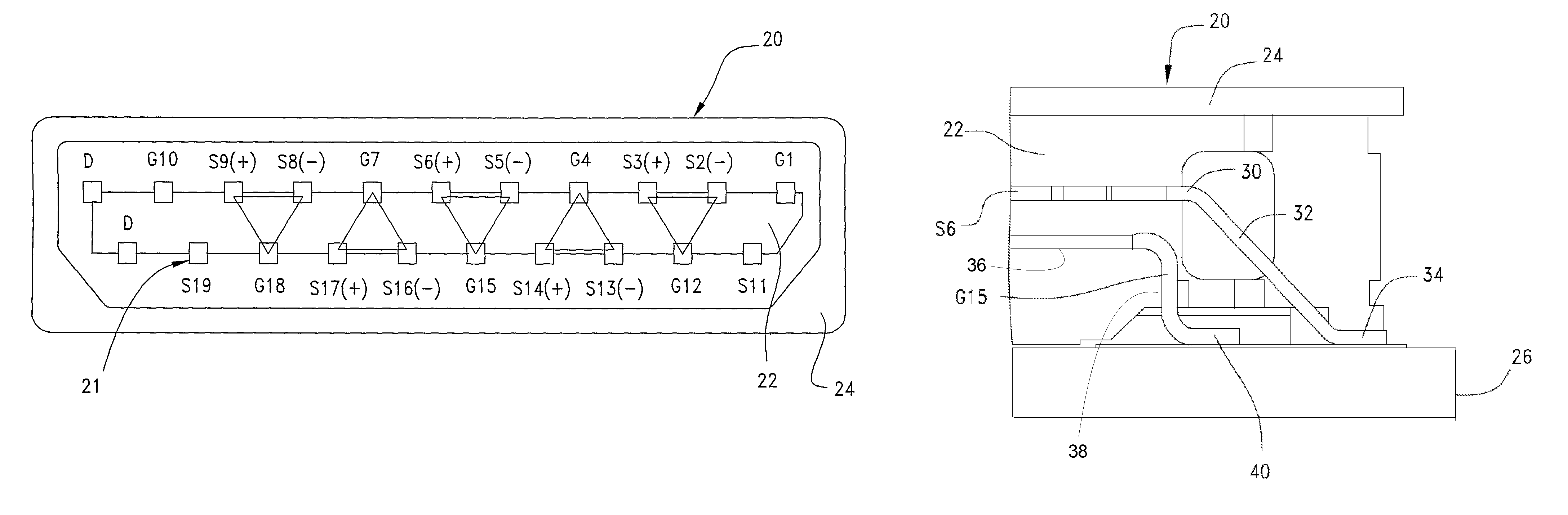
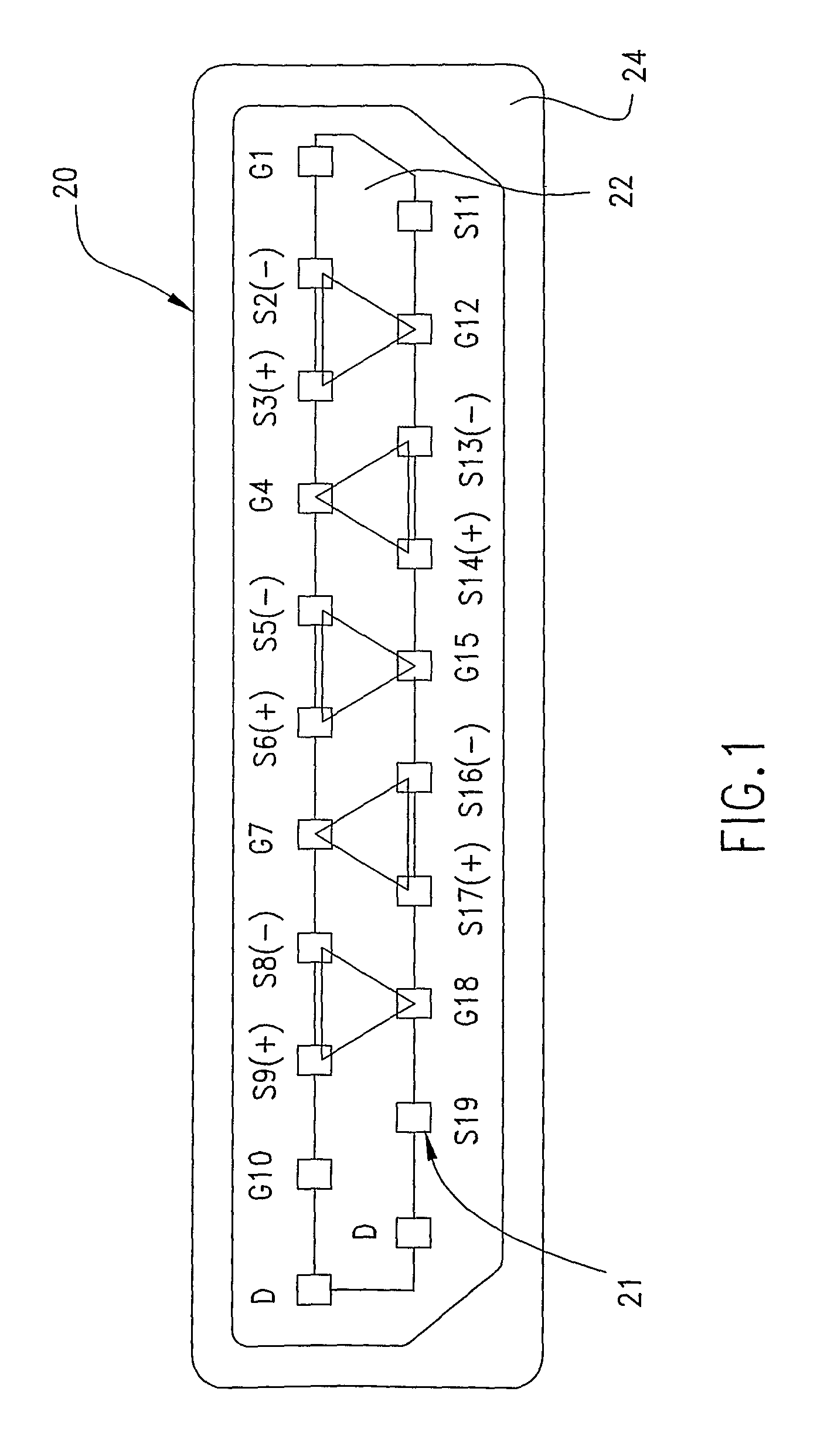
[0034]the body routing is shown in FIGS. 4 and 5. Terminal S5 and S6 are positioned in the first row and terminal G15 is positioned in the second row so to form the triangular relationship between the terminals that extends from the mating interface to the board interface. Bodies of the first row of terminals S, G extend outwardly from the insulator 22, are linearly aligned, and spaced apart from each other. The body of each terminal S, G in the first row has a first portion 30 which extends outwardly from the insulator 22 in a direction generally parallel to the board 26 to which the connector 20 is 20 mounted and a second portion 32 which extends at an angle relative to the first portion 30 downwardly toward the board 26. The terminal further includes a tail portion 34 which extends outwardly from the second portion 32 in a direction away from the connector 20. The tail portion 34 of each terminal S, G in the first row is soldered to the board 26. As depicted, the tails in the fir...

second embodiment

[0036]A second embodiment is shown in FIGS. 6 and 7. Bodies of the first row of terminals S, G extend outwardly from the insulator 22, are linearly aligned, and spaced apart from each other. The body of each terminal S, G in the first row has a first portion 30a which extends outwardly from the insulator 22 in a direction generally parallel to the board 26 to which the connector 20 is mounted and a second portion 32a which is generally perpendicular to the first portion 30a (e.g., is a vertical portion) and extends downwardly toward the board 26. The terminal further includes a tail portion 34a which extends generally perpendicular to the second portion 32a in a direction away from the connector 20. The tail portion 34a of each terminal S, G in the first row is soldered to the board 26.

[0037]Bodies of the second 20 row of terminals S, G extend outwardly from the insulator 22, are linearly aligned, and spaced apart from each other. The body of each terminal S, G in the second row has...

third embodiment

[0039]In a third embodiment, as depicted in FIGS. 8-19, terminals can be similarly mounted to a board via SMT in a manner that allows a triangular terminal (TT) arrangement to extend from the contact interface to the board mounting interface.

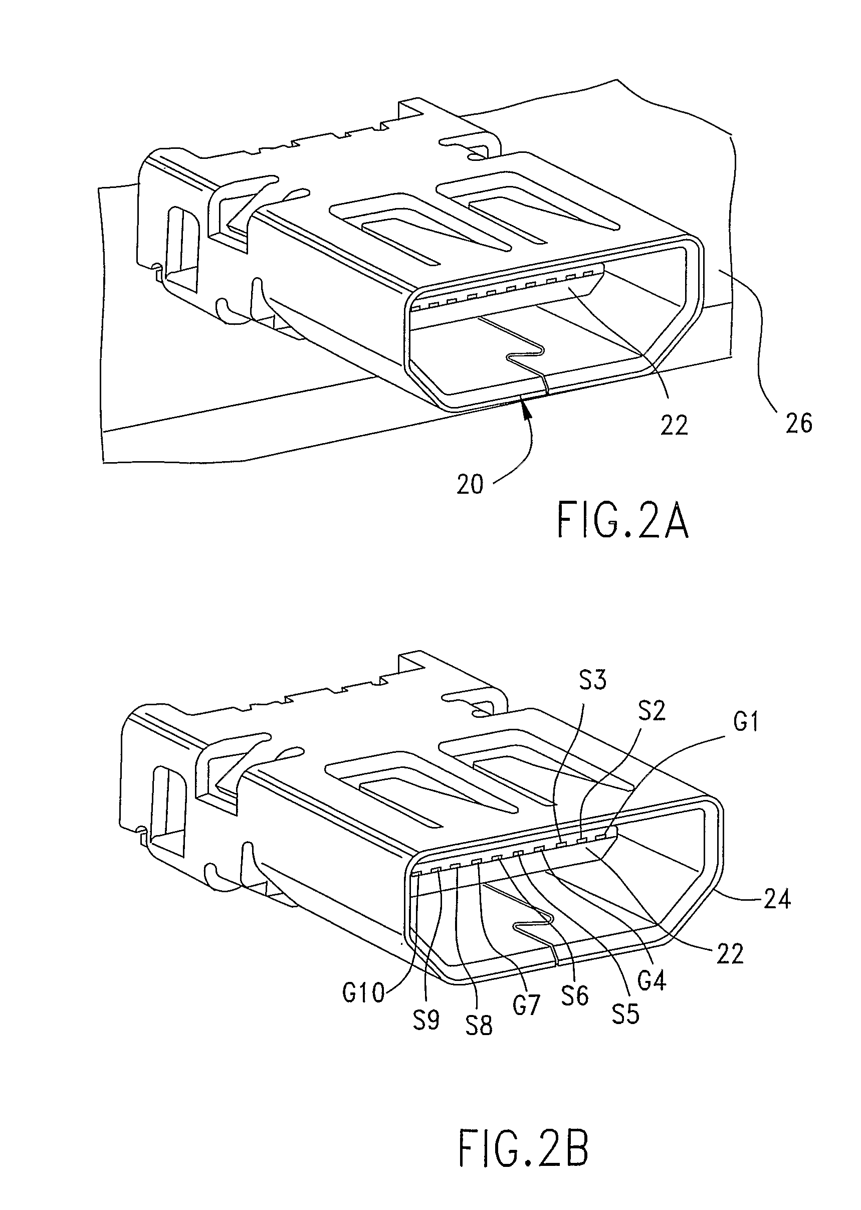
[0040]As depicted, connector 120 includes shield 124 with contacts 150 and terminals 121 mounted via SMT to a circuit board. An insulative housing 122 includes a tongue 122a that is positioned in the shield so as to provide a mating interface. Terminals 121 (which are individually labeled T1-T19) are positioned in two rows on the tongue 122a and the two rows extend through the connector from the mating interface to a board mounting interface. The terminals can provide three or more triangular terminal arrangements that each have two signal terminals and one ground terminal and are suitable for higher-speed data transmission.

[0041]The body of the terminals in the first row includes a first portion 130 that is supported by the housing and extends ...


PUM

PropertyMeasurementUnit
distanceaaaaaaaaaa
distanceaaaaaaaaaa
distanceaaaaaaaaaa

Abstract

A board-mountable connector is provided. The connector includes a shield and an insulative housing with a tongue. Terminals are supported by the housing in two rows and the rows extend from a mating interface to a board mounting interface. The terminals may be mounted to the board via surface mount technology in two rows that are at about 0.4 mm pitch. The two rows of terminals are configured in a signal, signal, ground triangular configuration so as to provide a triangular terminal arrangement that extends from the mating interface to the mounting interface.

Description

RELATED APPLICATIONS[0001]This application is a national phase of and claims priority to PCT Application No. PCT / IB2009 / 005418, filed Feb. 26, 2009, which in turn claims priority to U.S. Provisional Application No. 61 / 031,574, filed Feb. 26, 2008, both of which are incorporated herein by reference in their entirety.BACKGROUND OF THE INVENTION[0002]1. Field of the Invention[0003]The present invention relates to a board mounted electrical connector, more specifically to a board mounted electrical connector which has particular applicability for a 0.4 mm pitch connector in a High-Definition Multimedia Interface (HDMI).[0004]2. Description of Related Art[0005]As is known, input / output (I / O) connectors face competing demands. On the one hand, there is a common desire to provide more dense packing of terminals. On the other hand, there is an increasing desire for the data channels in the I / O connector to function at higher frequencies. These competing desires make it challenging to optimi...

Claims


Application Information

Patent Timeline
Patent Type & Authority Patents(United States)
IPC IPC(8): H01R13/648
CPCH01R12/725H05K3/00H01R12/707H01R12/57H01R23/6873Y10T29/49149H01R13/658H01R12/00
Inventor SOMMERS, SCOTT D.REGNIER, KENT E.KAMARAUSKAS, MICHAEL R.BANAKIS, EMANUEL G.FROMM, GALEN F.
Owner MOLEX INC
Why Eureka
Try Eureka