
Filter pipeline

a filter pipeline and filter technology, applied in the direction of filtration separation, combustion air/fuel air treatment, separation process, etc., can solve the problems of complex and cost-intensive filter pipeline manufacturing, difficult or even excluded to provide the required filter efficiency, and achieve the effect of simple assembly, low cost and different cross-sectional contours

Inactive Publication Date: 2013-08-13
MANN HUMMEL GMBH
View PDF7 Cites 4 Cited by
  • Summary
  • Abstract
  • Description
  • Claims
  • Application Information

AI Technical Summary

Benefits of technology

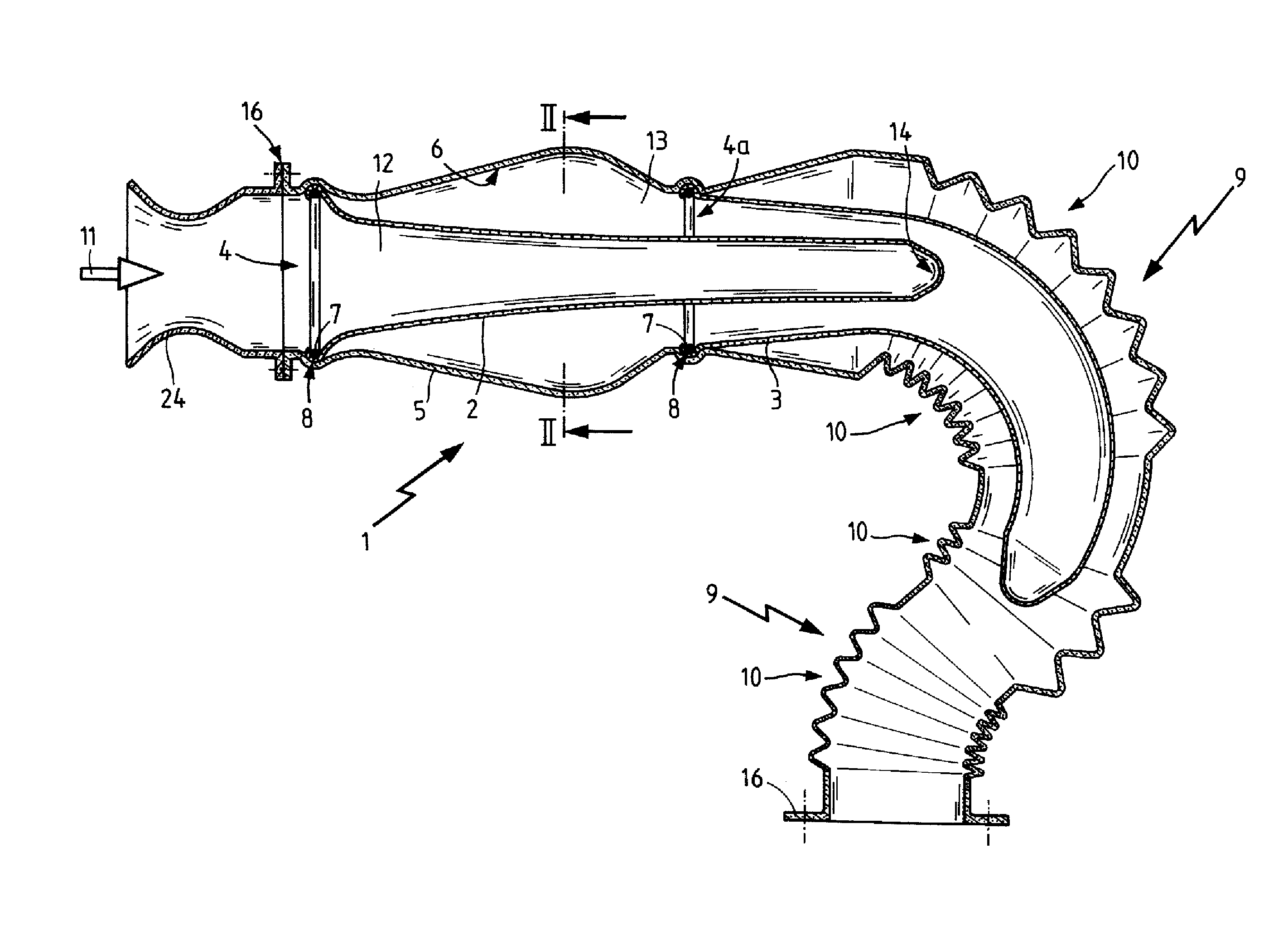
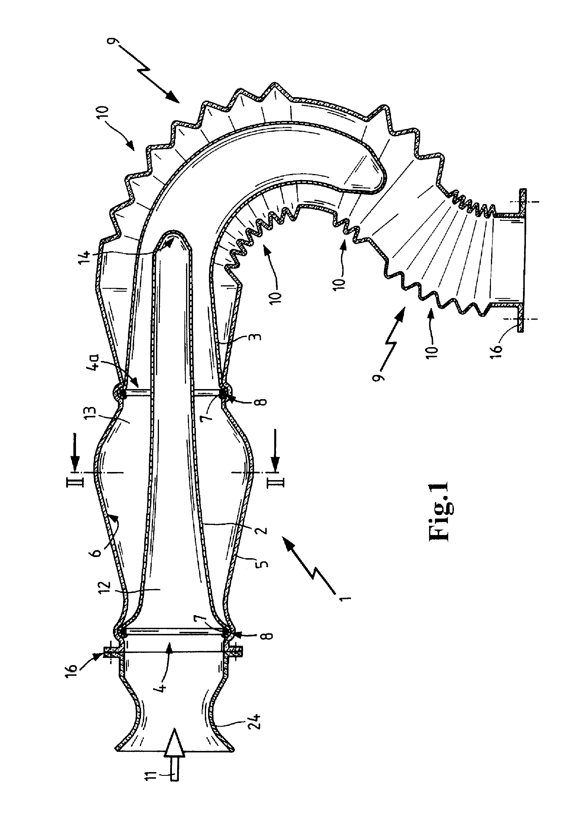
[0006]According to the invention a filter bag of a flexible material is provided as a filter element which filter bag is attachable in the area of its opening to the inner side of the pipeline. The filter bag extends from its opening to its bag bottom in the longitudinal direction of the pipeline. In this way, the length of the pipeline can be utilized and, as needed, by employing a filter bag of an appropriate length, a filter area can be made available that optionally extends to the end of the pipeline. The filter bag of flexible material can be pushed also through bends of the filter pipeline so that even in inaccessible bend areas a filtration can be performed in a simple way.
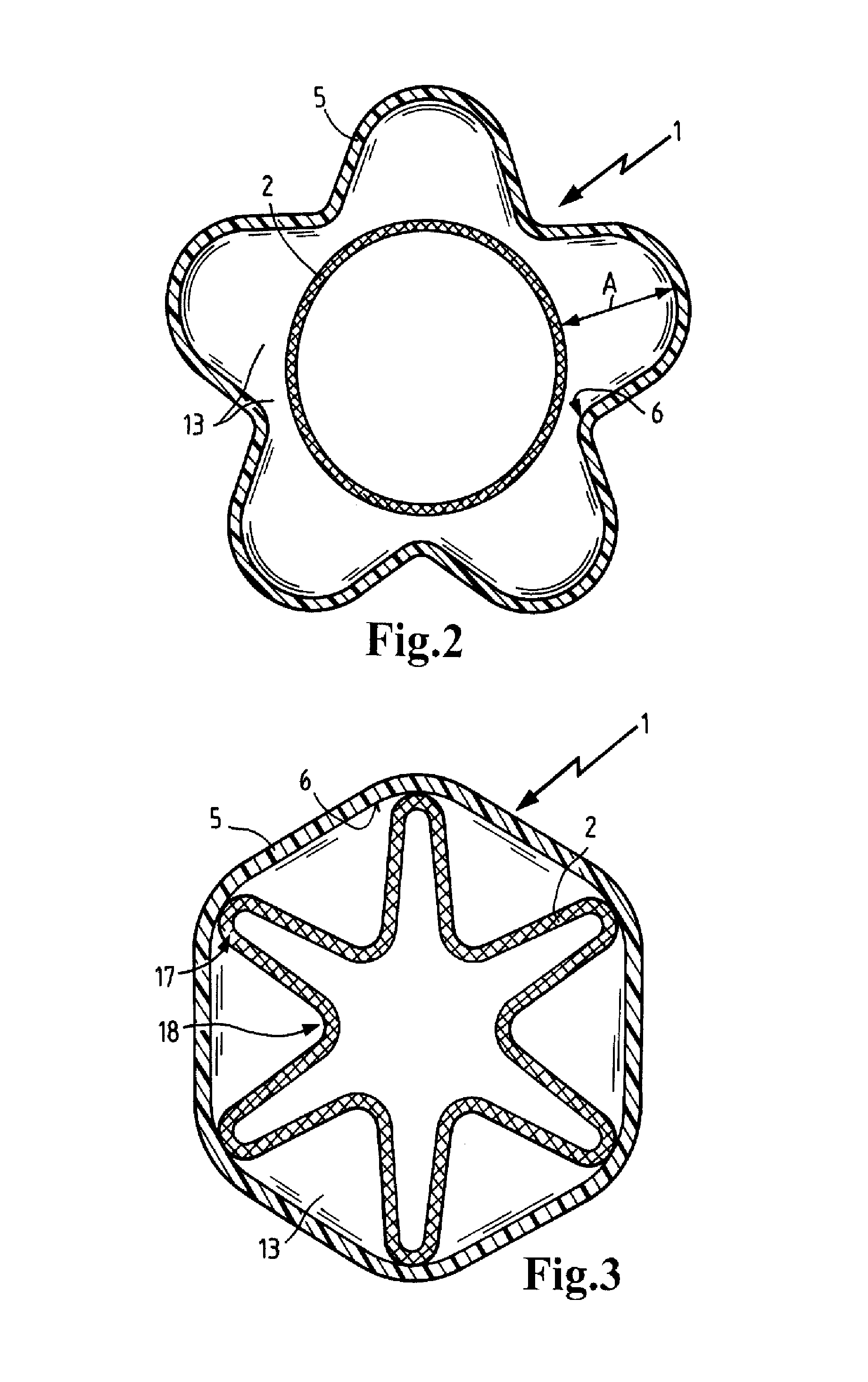
[0007]Expediently, the filter bag and the inner wall of the tubular body are shaped such that in the circumferential direction of the pipeline different spacings between the filter bag and an inner wall of the tubular body are provided so that it is prevented that the filter bag rests against the inner wall of the tubular body and so that there remains always a clean air space between the tubular body and the filter bag. Preferably, the filter bag and the inner wall of the tubular body have different cross-sectional contours. The filter bag can be advantageously prevented from resting against the inner wall of the tubular body by ribs that project inwardly from the tubular body.
[0008]An inexpensive manufacture of the filter pipeline can be achieved by designing the filter bag and / or the tubular body with a polygonal cross-sectional contour. By means of the polygonal cross-sectional contour it is ensured that a plurality of projections are formed as a result of the respective cross-sectional contour against which the filter bag can rest selectively about the circumference of the tubular body. In this connection, a star-shaped cross-sectional contour of the filter bag and / or of the tubular body is particularly advantageous.
[0009]In a preferred embodiment the filter bag is provided with attachment means for attaching it to the filter pipeline so that the filter bag can be attached in a simple way during assembly of the filter pipeline in the interior of the tubular body. In this connection, a clip-on connection provides a particularly simple assembly when the filter bag in the area of its opening is provided with an annular element that surrounds the opening which annular element can be locked in a securing groove provided on the tubular body. In this connection, the annular element can be embodied as an elastic spring ring. Alternatively or additionally, the tubular body can be produced from an elastically expandable material at least in the area of the securing groove. The tubular body is expediently manufactured of a mixture of thermoplastic synthetic material and an elastic synthetic material wherein an inexpensive manufacture is possible by extrusion of synthetic material or extrusion blow molding. In this connection, the plastic tubular body can be shaped in a simple manufacturing process so as to have the required cross-sections. In this connection, a thermoplastic elastomer (TPE) is employed as an elastic synthetic material wherein the use of polyamide (PA) or in particular polypropylene (PP) is preferred. Polypropylene may be partially filled in this connection and, in particular, may contain a proportion of talcum.
[0010]By extrusion of synthetic material or extrusion blow molding, the tubular body can be produced in a simple way as a monolithic part so that a part is produced that can be easily handled and integrated with minimal assembly expenditure in the intake manifold. By means of employing in accordance with the invention a filter bag of flexible material, no cross-sectional enlargements are needed for the use of the filter element because the required filter area is achieved primarily by means of the length of the filter bag in the longitudinal direction of the filter pipeline. In this way, it is possible to produce inexpensively endless pipe systems without great cross-sectional jumps wherein high manufacturing speeds with uniform quality can be achieved.
[0013]By arranging several filter bags sequentially, the filter efficiency can be effectively increased while requiring minimal space because the filter bags with their filter bottoms pass through the openings of the respectively filter bag arranged downstream and partially extend in the interior of the filter bag arranged downstream. In this connection, filter bags with different pore structures can be sequentially arranged in a simple way, for example, as a coarse filter and an adjoining fine filter. The filter bags are arranged at a spacing relative to one another in the longitudinal direction of the filter pipeline so that between the filter layers spaces for receiving the air that has just been filter will result. A simple and thus quick and inexpensive assembly is provided by attachment of the filter bags in a mounting part wherein the mounting part is inserted with the filter bags attached thereto into the pipeline. The mounting part itself is designed as a pipe and is connected to the adjoining end sections of tubular bodies, respectively. In this way, for maintenance of the filter pipeline at regular intervals the mounting part can be exchanged together with the filter bags with a few manipulations and new filter bags can be inserted.

Problems solved by technology

In the usual applications of filter pipelines in a motor vehicle, in lawn mowers or even in compressors, there is however only a very limited space available so that providing the required filter efficiency is often difficult or even excluded.
Moreover, the manufacture of filter pipelines with increased filter area is complex and cost-intensive because expensive filter elements such as round filter elements or compact filter elements must be used.

Method used


Image

  • Filter pipeline
  • Filter pipeline
  • Filter pipeline

Examples


Embodiment Construction

[0023]FIG. 1 shows the cross-section of a filter pipeline 1 for the intake manifold of an internal combustion engine, not illustrated, comprising a tubular body 5 that is produced continuously by extrusion blow molding. The tubular body 5 is designed as a monolithic part and is connected with the flanges 16 provided at its ends to tubular sockets 24 of the intake manifold or to the throttle.

[0024]The tubular body 5 has sections embodied with folds 10 or crease folds so that the tubular body is bendable in these sections 9. Taken-in air passes through the tubular body 5 in the longitudinal direction 11 wherein the incoming polluted air is guided through the filter bags 2, 3. The filter bags are comprised of nonwoven material, paper or other filtration media and are therefore flexible. In the present embodiment two filter bags 2, 3 are provided and spaced apart from one another in the longitudinal direction 11. The filter bags are attached with their rims in the area of opening 4 on t...


PUM

PropertyMeasurementUnit
flexibleaaaaaaaaaa
filter poresaaaaaaaaaa
elasticaaaaaaaaaa

Abstract

A filter pipeline for an air intake system of an internal combustion engine has a tubular body and a filter element arranged in the tubular body. The filter element is a filter bag of a flexible material that has an opening and is attachable in the area of the opening to the tubular body. The filter bag and an inner wall of the tubular body are provided with ribs projecting inwardly from the tubular body such that in a circumferential direction of the pipeline different spacings are provided between the filter bag and the inner wall of the tubular body.

Description

CROSS REFERENCE TO RELATED APPLICATIONS[0001]The present application is a CIP of U.S. Ser. No. 12 / 280,555 filed Aug. 24, 2008, now U.S. Pat. No. 8,029,586 B2, which is a US National Stage Entry of PCT / EP2007 / 051422 filed Feb. 14, 2007. U.S. Ser. No. 12 / 280,555 and PCT / EP2007 / 051422 are incorporated herein by reference in their entirety and to the fullest extent of the law. U.S. Ser. No. 12 / 280,555 (PCT / EP2007 / 051422) claims the benefit under 35 USC 119 of foreign application DE 20 2006 003 137.5 filed in Germany on Feb. 24, 2006.TECHNICAL FIELD[0002]The invention relates to a filter pipeline, in particular for the air intake system of an internal combustion engine, comprising a tubular body in which at least one filter element is received therein for filtering intake air.BACKGROUND OF THE INVENTION[0003]Filter pipelines are utilized in the air intake system of internal combustion engines in order to guide the taken-in ambient air through a filter element and in order to supply in th...

Claims


Application Information

Patent Timeline
Patent Type & Authority Patents(United States)
IPC IPC(8): B01D46/52
CPCB01D46/02B01D2279/60
Inventor LINHART, JOCHENBAUER, SASCHAFASOLD, MICHAEL
Owner MANN HUMMEL GMBH
Learn More