Firefightingexhaust shaft structure with resting function

A technology for exhaust wells and fire protection, which is applied to underwater structures, infrastructure engineering, building components, etc.

Pending Publication Date: 2019-07-19
CHINA CONSTR ENG DESIGN GROUP
View PDF0 Cites 0 Cited by
  • Summary
  • Abstract
  • Description
  • Claims
  • Application Information

AI Technical Summary

Problems solved by technology

In daily life, when going out for a walk and needing a rest, if there is an exhaust shaft nearby, you can only stand and lean, and you cannot sit down to completely relax your body and rest

Method used


Image

  • Firefightingexhaust shaft structure with resting function
  • Firefightingexhaust shaft structure with resting function
  • Firefightingexhaust shaft structure with resting function

Examples


Embodiment Construction

[0036] The present invention will be described in further detail below in conjunction with the accompanying drawings.

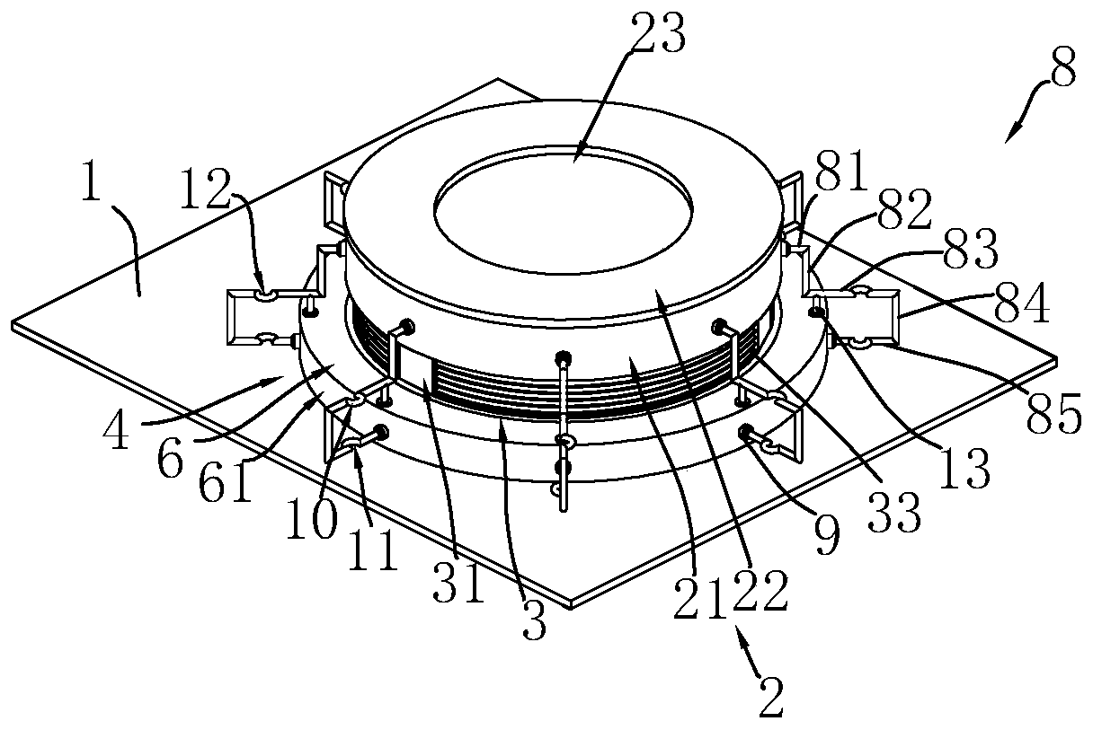
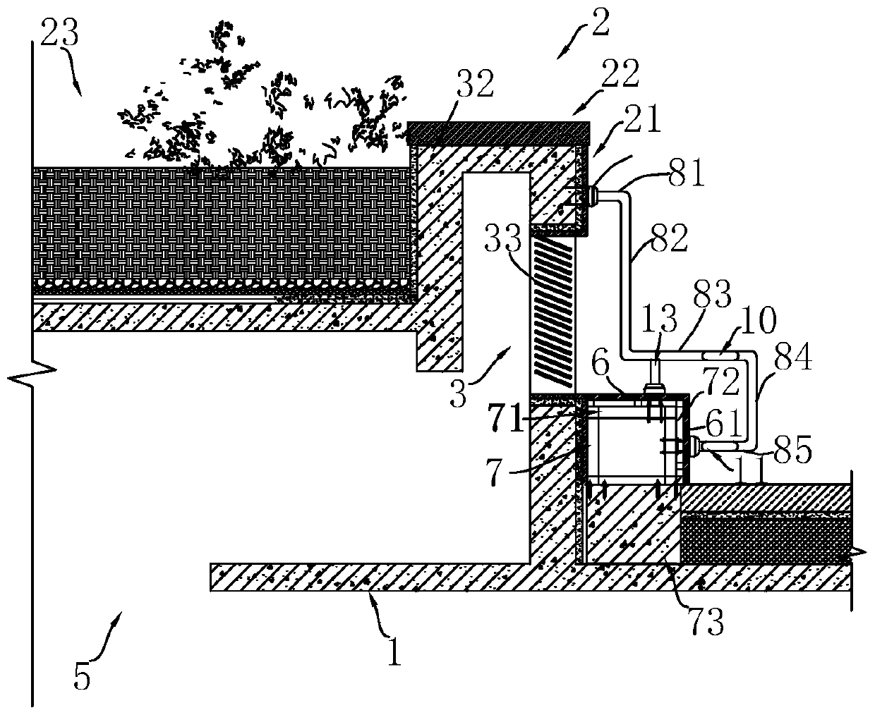
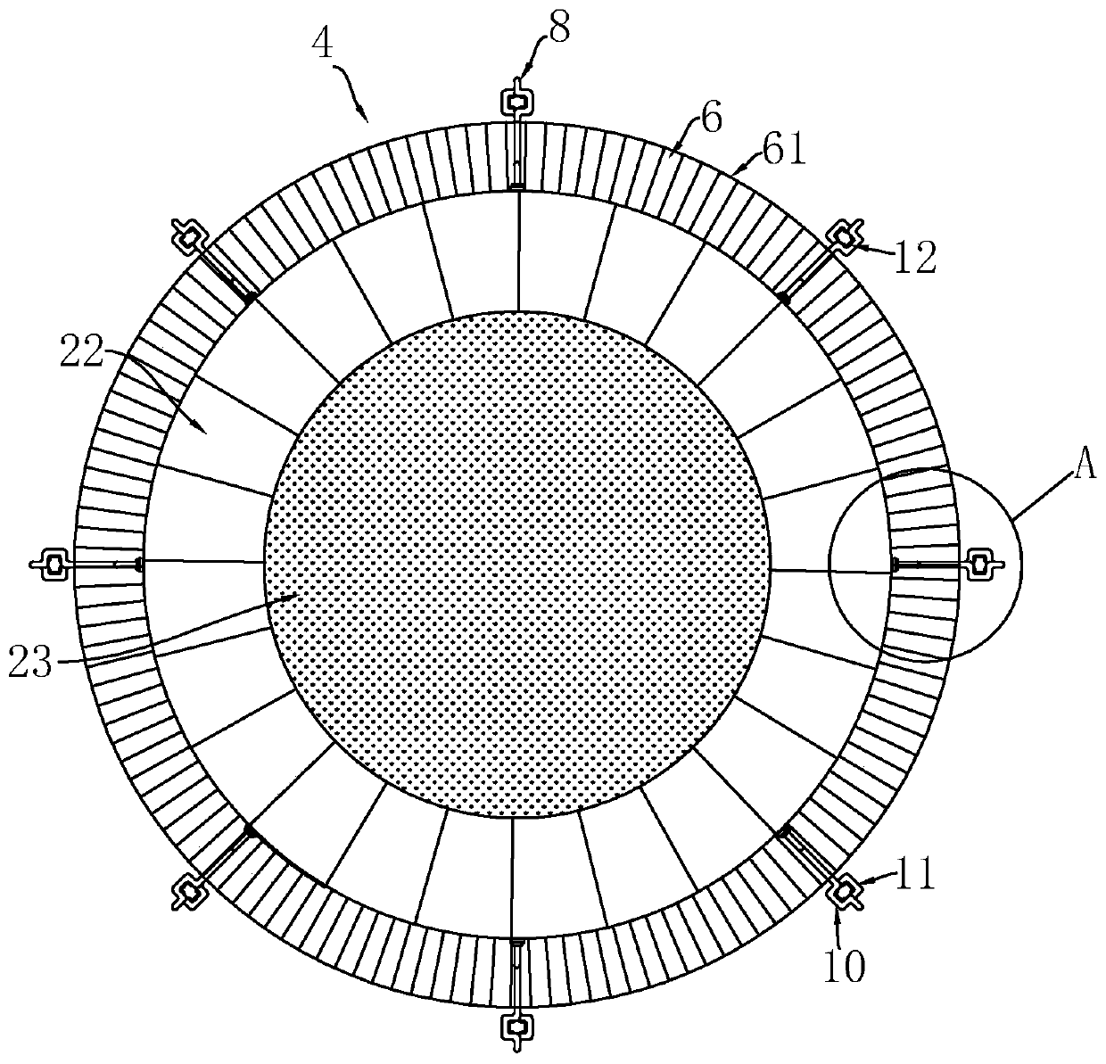
[0037] refer to figure 1 and figure 2 , is a fire-fighting exhaust shaft structure that can be used for rest disclosed by the present invention, comprising an indoor roof 1, a circular exhaust shaft chamber 2 arranged on the top board 1, a vent 3 provided on the exhaust shaft chamber and The seat 4 that is arranged on the outer peripheral surface of the exhaust shaft. The top plate 1 is provided with a top plate tuyere 5, the top plate 1 is a reinforced concrete structure, and the circular exhaust well chamber 2 is arranged on the top plate tuyere 5, and the top plate tuyere 5 connects the indoor space with the circular exhaust well chamber 2; the circular exhaust well chamber The chamber 2 includes a well wall 21 vertically arranged on the top plate 1 and a well cover 22 covered on the well wall 21. A vent 3 is provided on the well wall 21. Several suppor...


PUM


Abstract

The invention relates to a firefightingexhaust shaft structure with a resting function, which comprises a top plate arranged on the top surface of a basement.A top plate air opening is opened in the top plate, a circular exhaust shaft chamber is fixedlyformed above the top plate air openingon the top plate,the exhaust shaft chamber comprises a well wall vertically arranged on the top plate and a manhole cover covering the well wall, a ventilation opening is opened in the well wall, and a plurality of support columns are arrange in the ventilation opening; thefirefightingexhaust shaft structurewith the resting functionfurther comprises seatsarrangedin an encircling mode on the outer circumferential surface of the exhaust shaft chamber, and the seatsare flush with the bottom surface of theventilation opening; a plurality of armrests are arranged on the outer circumference surface of the circular exhaust shaft chamberat intervals, one ends of the armrests arefixedly consolidated with the outer circumference surface of the circular exhaust shaft chamber. and the other ends are fixedly consolidated with the seats. The firefightingexhaust shaft structure with the resting function has the effect that the function of rest is provided for a person whenthe exhaust shaft exhaustsair.

Description

technical field [0001] The invention relates to the technical field of fire-fighting ventilation, in particular to a fire-fighting ventilation shaft structure for rest. Background technique [0002] At present, with the rapid development of social economy, the number of underground buildings is increasing day by day, and people's activities in underground buildings are increasing, such as underground garages, underground supermarkets, underground shopping malls, etc. In order to ensure the normal use of personnel in underground rooms, it is necessary to ensure that Building good air quality. [0003] The general design method of the existing underground exhaust system is: the indoor air is discharged into the exhaust shaft through the exhaust fan, and the air in the exhaust shaft rises through the roof of the basement to the exhaust shaft room where the ground is higher than the floor level. , Most of the exhaust shaft chambers are hollow cubes, and the side of the exhaust ...

Claims


Application Information

Patent Timeline
Patent Type & Authority Applications(China)
IPC IPC(8): E04F17/04E02D29/045
CPCE02D29/045E04F17/04
Inventor 唐悦兴王蕊
Owner CHINA CONSTR ENG DESIGN GROUP
Why Eureka
Try Eureka