Portable electronic device

a portable electronic device and door design technology, applied in the field of portable electronic devices, can solve the problems of increasing the labor costs of companies, affecting the quality of electronic devices, and the cost of bolts, screws or latches is a large number of costs, so as to reduce the cost of components

Active Publication Date: 2013-08-13
INVENTEC CORP
View PDF10 Cites 8 Cited by
  • Summary
  • Abstract
  • Description
  • Claims
  • Application Information

AI Technical Summary

Benefits of technology

[0011]In another embodiment disclosed herein, each of the pair of sliding rails has a block member at an end for preventing the latch from sliding out of the pair of sliding rails.
[0018]Thus, the door design of the portable electronic device disclosed herein only utilize a single door to cover a bottom surface of the main body and the door is equipped with two latches and omitted with conventional bolts or screws so as to reduce the component costs as well as the assembly complexities of the portable electronic device.

Problems solved by technology

For the companies who manufacture a huge number of notebooks, the costs of bolts, screws or latches are somewhat a large number of costs.
For an assembly line of the companies who manufacture a huge number of notebooks, the more components each notebook has, the more labor costs the companies should pay for.

Method used


Image

  • Portable electronic device
  • Portable electronic device
  • Portable electronic device

Examples


Embodiment Construction

[0030]Reference will now be made in detail to the present preferred embodiments of the invention, examples of which are illustrated in the accompanying drawings. Wherever possible, the same reference numbers are used in the drawings and the description to refer to the same or like parts.

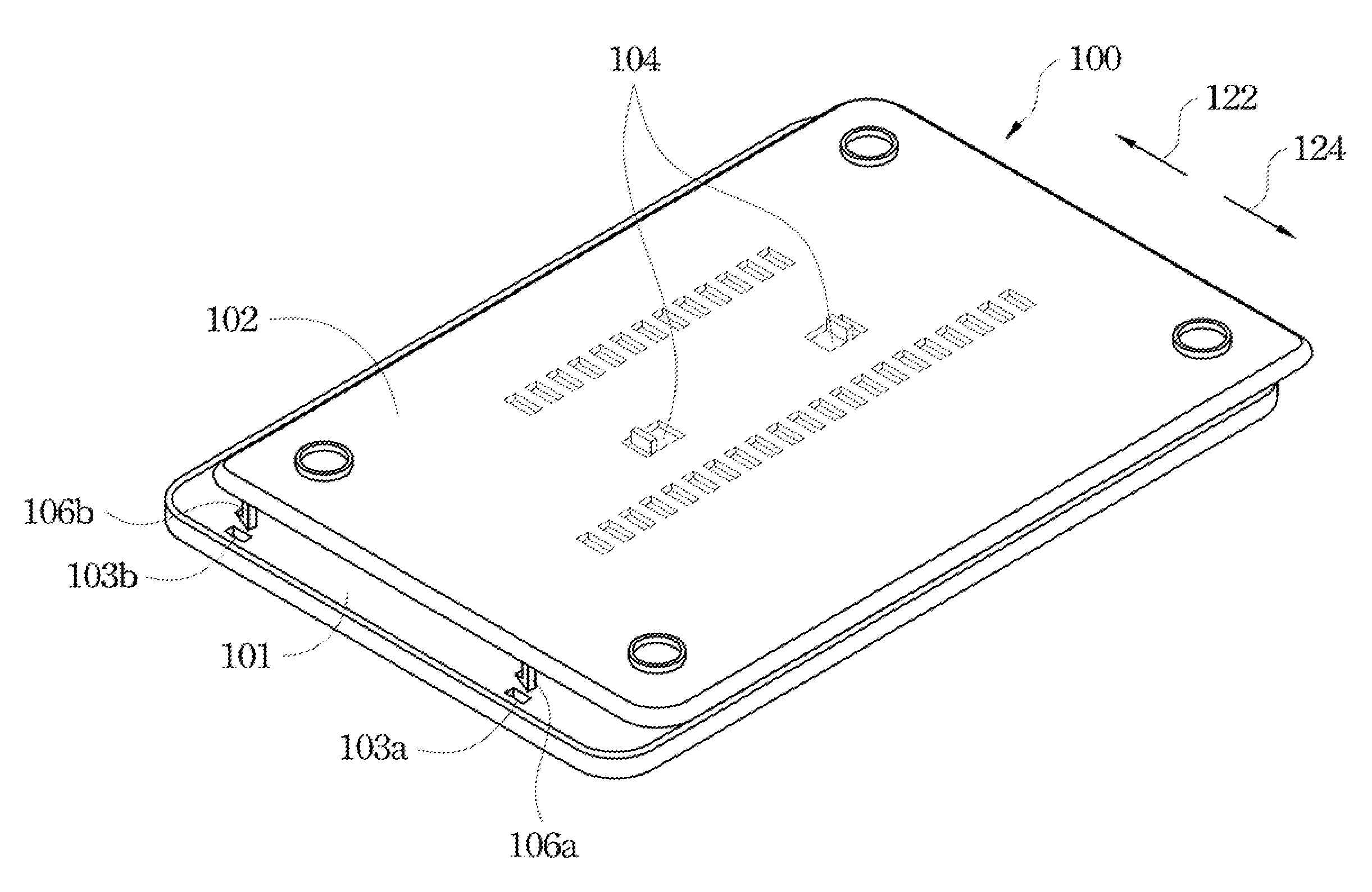
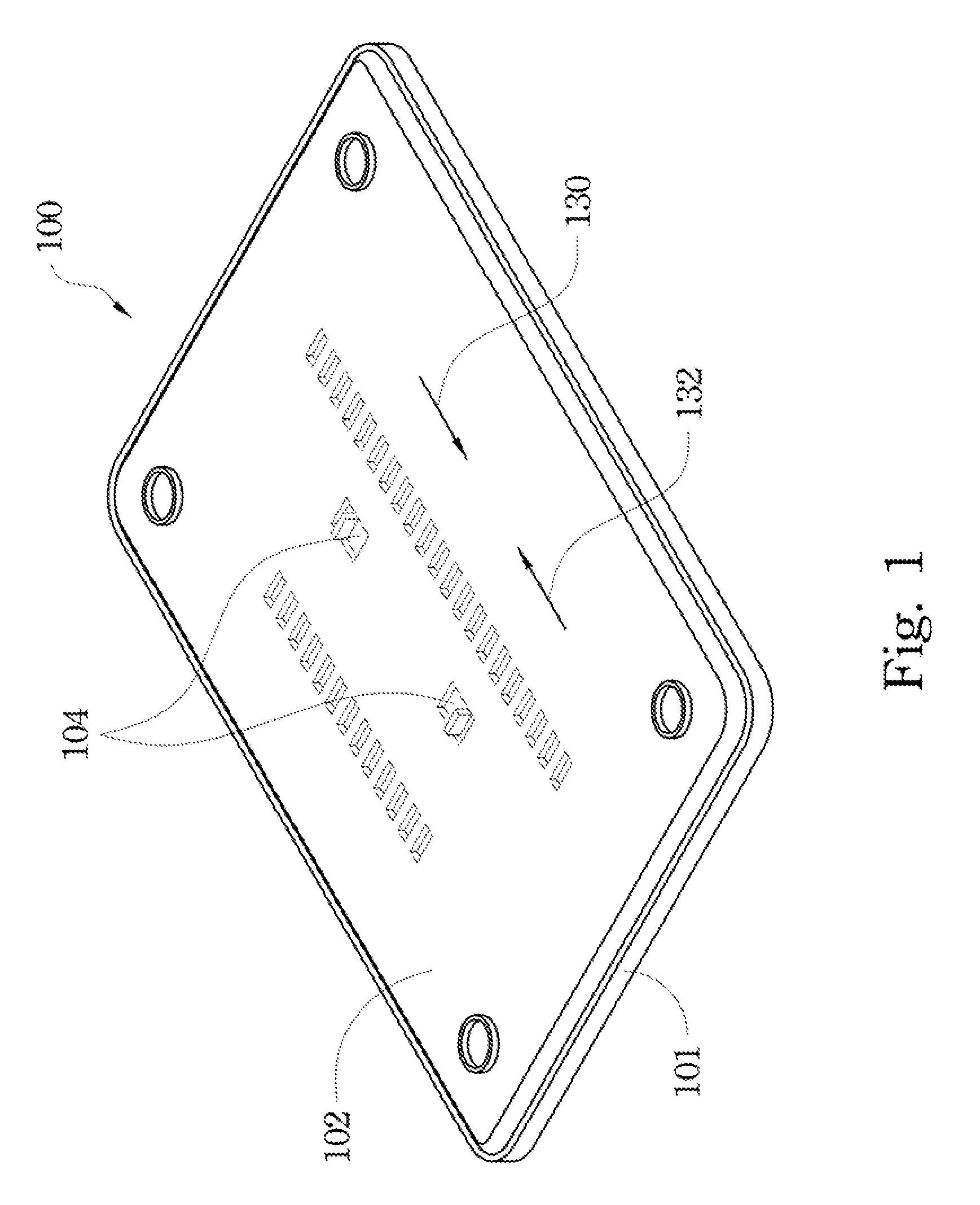
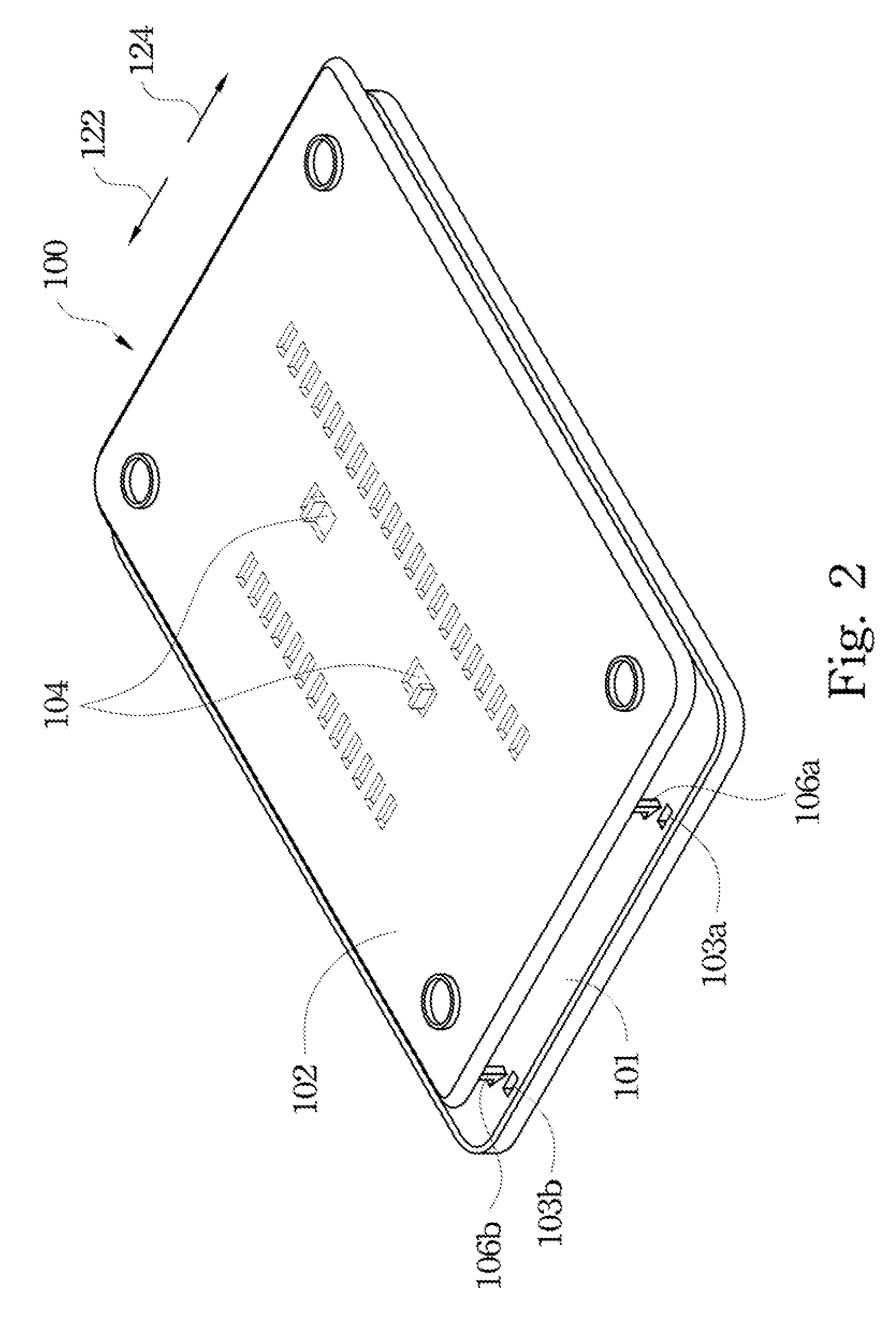
[0031]FIG. 1 illustrates a bottom view of a portable electronic device according to one preferred embodiment of this invention. FIG. 2 illustrates the portable electronic device in FIG. 1 with its door removed from its main body. The portable electronic device 100 includes a main body 101 and a door 102. The door 102 is detachably connected with a bottom surface of the main body 101. The door 102 has a pair of latches 104 to lock or unlock the door 102 to the main body 101. When the door 102 is desired to be assembled to the bottom surface of the main body 101, the door102 is moved toward the bottom surface of the main body 101 to insert its engaging hooks (106a, 106b), which are located at two edges...


PUM

PropertyMeasurementUnit
resilientaaaaaaaaaa
areaaaaaaaaaaa
timeaaaaaaaaaa

Abstract

A portable electronic device includes a main body, a door and a latch. The main body includes a positioning concave area on a bottom surface thereof. The positioning concave area has a cutout at a first edge, and an inclined surface and a guide edge at an opposite edge. The door is detachably connected with the bottom surface of the main body. The latch is slidably connected with a through hole of the door. The latch has an engaging portion and a guiding portion at two opposite ends. When the door is assembled to the bottom surface of the main body, the engaging portion inserts into the cutout. When the door is taken apart from the bottom surface, the engaging portion is removed from the cutout, and the guiding portion slides along the guide edge to move the door along a direction perpendicular to a long axis of the latch.

Description

RELATED APPLICATIONS[0001]This application claims priority to Taiwan Application Serial Number 100100375, filed Jan. 05, 2011 which is herein incorporated by reference.BACKGROUND[0002]1. Field of Invention[0003]The present invention relates to a door design of a portable electronic device.[0004]2. Description of Related Art[0005]A portable electronic device, e.g. a notebook computer, has multiple removable covers to be easily removed by users or engineers when some components inside the computers need to be replaced or repaired. In a conventional design, these removable covers are fastened to a case of the portable electronic device by means of bolts or screws. If these removable covers are not fastened by means of bolts or screws, at least a latch or the like are needed to fasten them. Each notebook computer is usually equipped with two or more removable covers, each cover needs at least two bolts, screws or latches to secure themselves.[0006]For the companies who manufacture a hug...

Claims


Application Information

Patent Timeline
Patent Type & Authority Patents(United States)
IPC IPC(8): G06F1/16H01M2/10
CPCG06F1/1613G06F1/1656
Inventor CHEN, DONG-SENWANG, JEN-HSIANGLIN, CHUN-CHI
Owner INVENTEC CORP
Why Eureka
Try Eureka