Vehicle periphery display device and method for vehicle periphery image

a technology for vehicle periphery and display device, which is applied in the field of vehicle periphery display device and vehicle periphery image, can solve the problem of large image processing load

Inactive Publication Date: 2013-08-20
DENSO CORP +1
View PDF31 Cites 11 Cited by
  • Summary
  • Abstract
  • Description
  • Claims
  • Application Information

AI Technical Summary

Benefits of technology

[0007]In view of the foregoing and other problems, it is an object of the present invention to produce a vehicle periphery display device capable of facilitating indication of an object such as a white line around a vehicle outside of a view area. It is another object of the present invention to produce a method for indicating a vehicle periphery image.

Problems solved by technology

Accordingly, processing load for the image processings becomes large.

Method used


Image

  • Vehicle periphery display device and method for vehicle periphery image
  • Vehicle periphery display device and method for vehicle periphery image
  • Vehicle periphery display device and method for vehicle periphery image

Examples


embodiment

[0020](Embodiment)

[0021]The vehicle periphery display device is capable of indicating a condition around a vehicle and assisting a driving operation of a driver by providing an indication on a screen. A vehicle rear display device, which is one example of the vehicle periphery display device, will be described with reference to FIGS. 1 to 9. The vehicle rear display device indicates a composite image including a present actual image on a rear side of the vehicle, an image of the vehicle, and a periphery of the vehicle generated according to a previous image to be continuous with the actual image. Thus, the vehicle rear display device is capable of notifying a driver of an accurate position of the self-vehicle and efficiently assisting rearward parking of the vehicle.

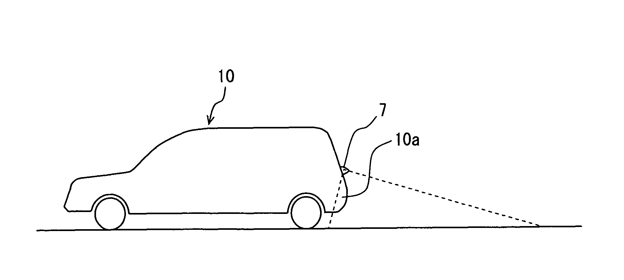
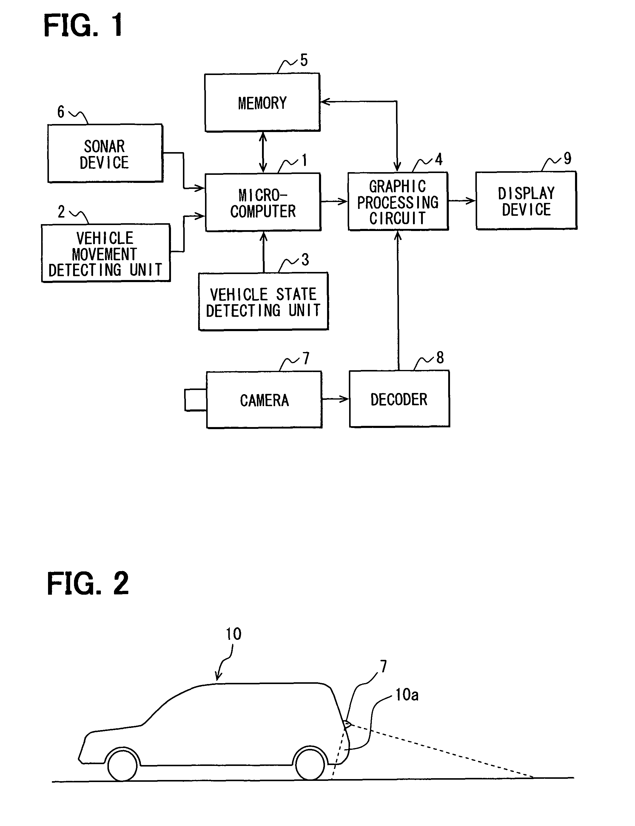
[0022]FIG. 1 is a block diagram showing a structure of the vehicle rear display device. FIG. 2 is a schematic view showing a physical relationship between a vehicle 10 and a camera 7. The vehicle rear display device incl...


PUM


Abstract

An imaging unit photographs an image of a periphery of the vehicle. An object detection unit obtains image information related to a brightness or a color of the image and position information on the obtained image from the image and detects object from the image information according to a specific feature of the image. A storing unit prestores a vehicle image and history data, which include the image information associated with the position information. A graphic unit overlaps the vehicle image and an image produced according to the history data and converts the overlapped image to be viewed from a predetermined viewpoint. A peripheral image display region indicates a present periphery of the vehicle. A history display region is adjacent to the peripheral image display region for indicating the converted image and the detected object at a position according to the position information.

Description

CROSS REFERENCE TO RELATED APPLICATIONS[0001]This application is based on and incorporates herein by reference Japanese Patent Application No. 2009-75035 filed on Mar. 25, 2009.FIELD OF THE INVENTION[0002]The present invention relates to a vehicle periphery display device for indicating a peripheral condition of a vehicle. The present invention further relates to a method for indicating a vehicle periphery image.BACKGROUND OF THE INVENTION[0003]Conventionally, for example, JP-A-2003-189291 and JP-A-2006-7498 disclose an art for indicating a composite view by combining an image, which is obtained by imaging a peripheral condition of a rear side of a self-vehicle in real time, with both an image indicating a view, which is moved to the outside of a view area while the self-vehicle moves rearward, and an image of the self-vehicle. Thus, a physical relationship between the self-vehicle and the peripheral condition are provided to a driver.[0004]According to the first conventional art de...

Claims


Application Information

Patent Timeline
Patent Type & Authority Patents(United States)
IPC IPC(8): H04N7/18
CPCB60R1/00B62D15/0275G06K9/00798B60R2300/304B60R2300/607B60R2300/70B60R2300/806G06V20/588
Inventor IMANISHI, MASAYUKIWAKAYAMA, NOBUHIKO
Owner DENSO CORP
Why Eureka
Try Eureka