LED light-emitting structure and light-emitting spike with same

A technology of light emission and road studs, which is applied to the semiconductor devices of light-emitting elements, roads, light sources, etc., can solve the problems of non-compression and impact resistance, poor structural strength, cumbersome manufacturing and installation, etc., and increase the compression and impact resistance performance, improve the shell structure, increase the effect of structural strength

Inactive Publication Date: 2020-06-09
方显峰
View PDF0 Cites 4 Cited by
  • Summary
  • Abstract
  • Description
  • Claims
  • Application Information

AI Technical Summary

Problems solved by technology

[0009] 1. The lamp bead is vertically upward or obliquely upward, and its light intensity distribution is unreasonable. A large part of the light energy is emitted upward through the top of the light slot, and the light intensity in the upward direction is relatively large, resulting in the visible distance of remote light Short, poor effect, low utilization rate of light energy, and short-range light can easily cause light interference and glare to pedestrians and non-motor vehicle drivers, and easily induce traffic accidents
[0010] 2. The wall thickness of the top part of the inverted V-shaped light emitting groove is thin, the structural strength is small, and the compression and impact resistance are not enough, which is easy to cause damage to the shell;
[0011] 3. The inverted V-shaped light emitting groove is not conducive to the injection molding process. The inverted V-shaped light emitting groove has a large stress and is easy to crack. In order to achieve a better remote lighting effect, it is necessary to adjust the installation angle and positioning of the straw hat lamp bead. Inconvenient, resulting in poor product consistency
[0012] To sum up, the existing luminous road studs all have unreasonable LED light emission structures, which lead to unreasonable light field distribution of the luminous light guide part of the road stud, which is not conducive to the distribution of light intensity ratio, and the light energy utilization rate is low. The long-distance lighting effect is poor, and the short-distance lighting is easy to cause light interference. Within the size limit of the existing traffic regulations, it is not easy to reduce the height of the road stud out of the road surface. The main disadvantage is that it cannot meet the diverse needs of roads, which seriously hinders the popularization and use of luminous road studs

Method used


Image

  • LED light-emitting structure and light-emitting spike with same
  • LED light-emitting structure and light-emitting spike with same
  • LED light-emitting structure and light-emitting spike with same

Examples


Embodiment 1

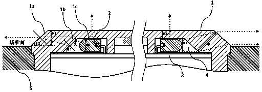
[0101] A solar luminous reflective raised road stud, comprising one transparent shell (110), one LED straw hat lamp (120), one partition (130), one air layer (140), and one accommodating cavity (150) , Bottom case one (160), retro reflector one (170), photovoltaic module one (180), control circuit one (190), energy storage element one (1100), such as Figure 5 —13 shown.

[0102] Transparent shell one (110):

[0103] Transparent shell one (110) is an injection-molded part similar to a rectangular parallelepiped with a downwardly opened cavity formed by a transparent PC through an injection process. The four corners of the top are recessed downward to form two sets of positive and back slopes with a height of 6mm and a thickness of 10mm. The outer slope (110a) and the inner slope (110b) of the slope are parallel to each other and are parallel to the top surface. It has an included angle of 45°. Between the inner slopes (110b) of each group, there is an arched top (similar to an inv...

Embodiment 2

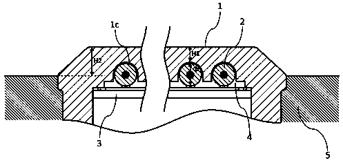
[0123] A solar luminous reflective raised road stud, comprising two transparent shells (210), two LED straw hat beads (220), two separators (230), two air layers (240), two retroreflectors (270), Photovoltaic module two (280), control circuit two (290), energy storage element two (2100), such as Figure 14 —17 shown.

[0124] Transparent shell two (210):

[0125] The second transparent shell (210) is an injection molded part of transparent PC with a downwardly opened cavity. Its shape is similar to a table body. The front and rear sides are respectively provided with opposite slopes that intersect the bottom surface at an angle of 30° and each has a convex groove. The left and right sides protrude outward in an arc shape and are respectively taped There is a mounting hole, the four corners of the top are recessed downward to form two sets of opposite slopes with a height of 6mm and a thickness of 9mm in front and back directions. The outer slopes of the slopes are two (210a) and t...

Embodiment 3

[0139] A buried solar luminous road stud, comprising three transparent shells (310), three LED straw hat beads (320), three partitions (330), three air layers (340), three top covers (361), and bottom Shell three (362), photovoltaic module three (380), control circuit three (390), energy storage element three (3100), external waterproof wire three, such as Figure 18 —21 shown.

[0140] Transparent shell three (310):

[0141] Transparent shell three (310) is a fully transparent PC shell, and the shape is similar to an inverted transparent ashtray. Its lower part is a petal-shaped column, and its top is provided with a cross-shaped upward convex corresponding to the cross-shaped window on the top cover three (361), and the four relatively sinking concave parts are provided with two sets of forward and backward , A relative inclined plane with a height of 6.5mm and a thickness of 10mm, the outer inclined plane 3 (310a) and the inner inclined plane 3 (310b) of the inclined plane are ...


PUM

PropertyMeasurementUnit
thicknessaaaaaaaaaa

Abstract

The invention discloses an LED light-emitting structure and a spike with the same. The LED light-emitting structure comprises a transparent shell (1), an LED luminous body (2) with a light condensingelement, a separation body (3) and an air layer (4), the LED luminous body (2) is packaged in the transparent shell (1) through the separation body (3), light emitted by the LED luminous body (2) is mainly condensed by the condensing element, incident by an inner inclined surface (1b), refracted by a side wall with a certain thickness, emitted by an outer inclined surface (1a), emitted in the horizontal direction, mainly emitted in the upward direction and supplemented by emitted in the horizontal direction, and the LED luminous body (2) emits light in the horizontal direction to generate a local structure capable of generating upward displacement. The horizontal emergent light intensity ratio is high, the light energy utilization rate is high, the structural design allowance delta H and the power supply design allowance are improved, the structural strength is high, the forming process of the shell is facilitated, the light emitting intensity ratio in the horizontal direction and theupward direction are reasonably distributed so as to be more suitable for different emphasis points of vehicles and pedestrians, and the diversified requirements of roads are well met.

Description

Technical field [0001] The invention relates to the field of light-emitting equipment, in particular to an LED light emitting structure and a light-emitting road stud with the structure. [0002] technical background [0003] Luminous road studs, also called luminous protruding road signs, are mainly installed on the road surface and have a luminous function. They mainly act as visual guidance or prompts for motor vehicle drivers and pedestrians, and can also act as auxiliary road lighting equipment. [0004] Most of the existing luminous road studs are mainly raised luminous road studs, which are mainly installed on the road surface. The highest point of the road stud is generally more than 20mm above the road surface; there are also buried luminous road studs whose main body is buried in the road surface when used. The top is flush with the road or slightly protrudes from the bottom. [0005] The main light-emitting structures of existing road studs are mainly summarized into two ca...

Claims


Application Information

Patent Timeline
Patent Type & Authority Applications(China)
IPC IPC(8): F21K9/20F21K9/60F21K9/69F21K9/68F21V13/00F21V19/00E01F9/559F21Y115/10
CPCE01F9/559F21K9/20F21K9/60F21K9/68F21K9/69F21V13/00F21V19/001F21Y2115/10
Inventor 方显峰
Owner 方显峰
Why Eureka
Try Eureka