PLL adjustment to find and maintain resonant frequency of piezo electric finger print sensor

a piezo electric finger print sensor and resonant frequency technology, applied in the field of optimizing the performance of biometric sensors, can solve the problems of degrading the performance and affecting the accuracy of the biometric sensor

Active Publication Date: 2013-08-20
SONAVATION INC
View PDF12 Cites 56 Cited by
  • Summary
  • Abstract
  • Description
  • Claims
  • Application Information

AI Technical Summary

Problems solved by technology

These conventional biometric sensors are also susceptible to temperature variations, air pressure, and humidity.
These changes lead to problems like variations in the sensor's resonant frequency and sensor accuracy, thus degrading sensor performance and resulting in a loss of information.
Conventional biometric sensors also suffer from manufacturing variations.
These variations in resonant frequency degrade sensor performance and lead to changes in signal level and bias of the sensor's output that are unmitigated by conventional processing circuits.

Method used


Image

  • PLL adjustment to find and maintain resonant frequency of piezo electric finger print sensor
  • PLL adjustment to find and maintain resonant frequency of piezo electric finger print sensor
  • PLL adjustment to find and maintain resonant frequency of piezo electric finger print sensor

Examples


Embodiment Construction

[0025]This specification discloses one or more embodiments that incorporate the features of this invention. The embodiment(s) described, and references in the specification to “one embodiment”, “an embodiment”, “an example embodiment”, etc., indicate that the embodiment(s) described may include a particular feature, structure, or characteristic, but every embodiment may not necessarily include the particular feature, structure, or characteristic. Moreover, such phrases are not necessarily referring to the same embodiment. Furthermore, when a particular feature, structure, or characteristic is described in connection with an embodiment, it is submitted that it is within the knowledge of one skilled in the art to effect such feature, structure, or characteristic in connection with other embodiments whether or not explicitly described.

Overview

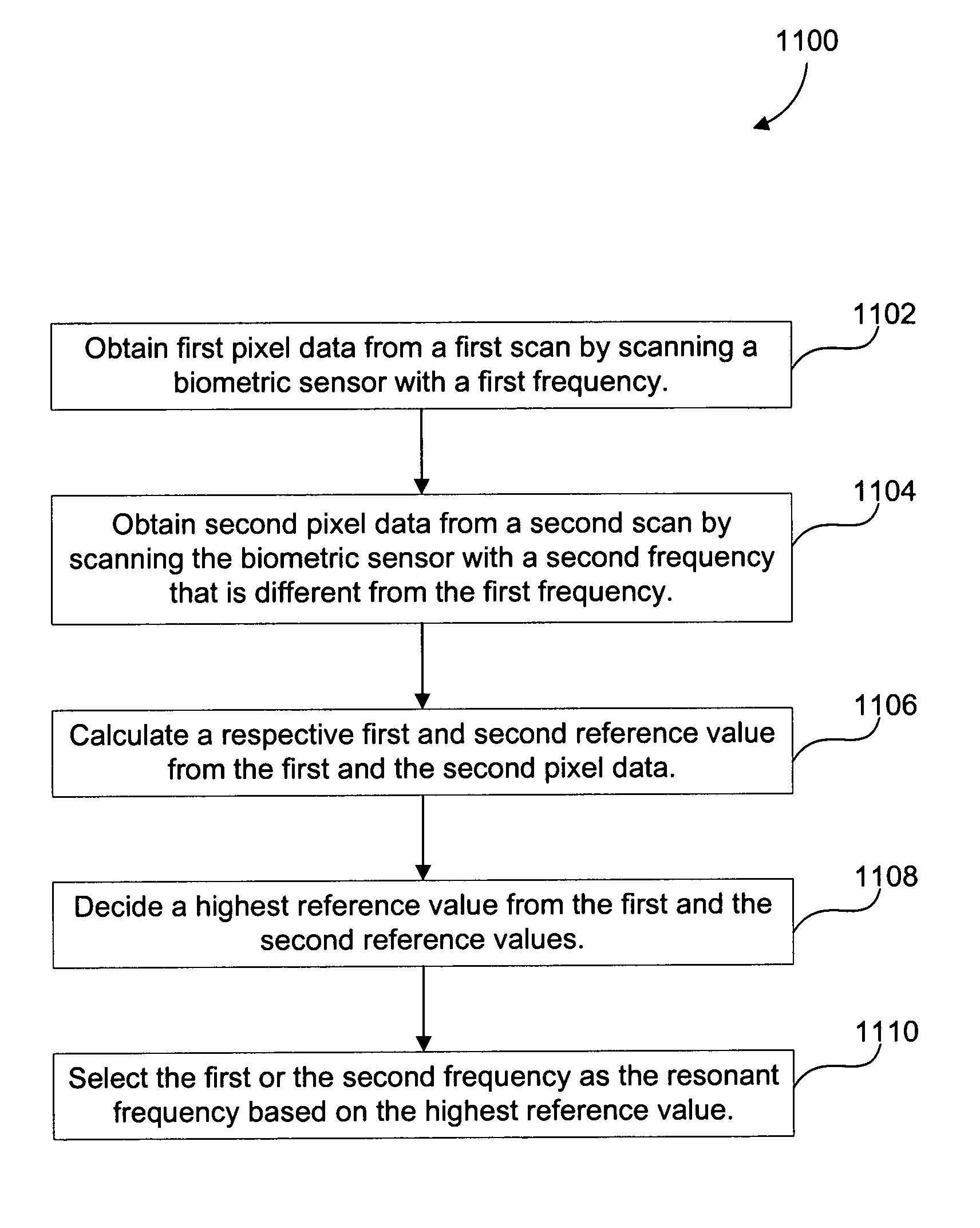
[0026]Embodiments provide methods, apparatus, and computer program products for determining a resonant frequency of a biometric sensor and using ...


PUM


Abstract

Provided is a method for determining a resonant frequency of a biometric sensor. The method includes obtaining first pixel data from a first scan by scanning the biometric sensor with a first frequency. Second pixel data is obtained from a second scan by scanning the biometric sensor with a second frequency that is different from the first frequency. A respective first and second reference value is calculated from the first and the second pixel data. A highest reference value is determined from the first and the second reference values. The first or the second frequency is selected as the resonant frequency based on the highest reference value.

Description

BACKGROUND OF THE INVENTION[0001]1. Field of the Invention[0002]The present invention relates to biometric sensor optimization. More particularly, the present invention relates to optimizing performance of a biometric sensor.[0003]2. Related Art[0004]In the field of biometric image analysis, traditional techniques sample an image, such as a fingerprint, as the image is sensed by a sensing mechanism. This sensing mechanism, such as a pressure and / or acoustic impedance-sensitive piezoelectric fingerprint sensor, captures images of the fingerprint. Ridges and valleys of the fingerprint vary pressure and / or acoustic impedance on different parts of the piezoelectric sensor to form light and dark portions of the captured image.[0005]The sensing ability of conventional biometric sensors, and their processing circuits, suffers from many shortcomings due to effects of changing environmental conditions, sensor manufacturing variations, and conditions of the fingers themselves. These conventio...

Claims


Application Information

Patent Timeline
Patent Type & Authority Patents(United States)
IPC IPC(8): G06K9/00H01L41/00H02N2/00
CPCA61B5/1172G06K9/0002G06V40/1306
Inventor CLARKE, DAVID BRIANLIAUTAUD, CHRISTIAN
Owner SONAVATION INC
Why Eureka
Try Eureka