Vehicle light with LED light source

a technology of led light source and vehicle light, which is applied in the direction of semiconductor devices of light source, fixed installation, light and heating apparatus, etc., can solve the problems of increasing the number of components, increasing the entire cost, and generating glare light, so as to prevent or suppress the generation of colored area

Inactive Publication Date: 2013-08-27
STANLEY ELECTRIC CO LTD
View PDF13 Cites 4 Cited by
  • Summary
  • Abstract
  • Description
  • Claims
  • Application Information

AI Technical Summary

Benefits of technology

[0013]When forming a synthesized light distribution pattern including a wide-area light distribution pattern and a middle-area light distribution pattern, such a conventional vehicle light as described above has required LED light sources for forming the wide-area light distribution pattern and the middle-area light distribution pattern, respectively. Namely, the vehicle light is usually provided with a large diffusion unit and a middle diffusion unit each having at least one LED light source. On the contrary, the vehicle light according to the above aspect can be composed of various reflectors and lenses appropriately designed and arranged so as to form an optimized, synthesized light distribution pattern including a wide-area light distribution pattern and a middle-area light distribution pattern with a common single LED light source. Accordingly, when compared with the conventional vehicle light, the vehicle light according to the above aspect can prevent the cost increase in terms of designing and parts number.
[0041]Accordingly, this configuration can prevent or suppress the generation of colored area (for example, blue) in a light distribution pattern near its cut-off line caused by direct light from an LED light source or reflected light therefrom that enters a lower-half portion of a lens below or almost below its optical axis from the diagonally upper side.

Problems solved by technology

Accordingly, there are problems in that design burden and the number of components increase, thereby increasing the entire cost.
In this case, since the focus of such a toroidal lens is a point focus or a group focus having focuses in an arc shape (strictly, due to the shape of the toroidal lens), light beams may be disadvantageously distributed in an area P1R as shown in FIG. 19 above the horizontal line H-H and near the opposite or oncoming vehicle road side, leading to generation of glare light.

Method used


Image

  • Vehicle light with LED light source
  • Vehicle light with LED light source
  • Vehicle light with LED light source

Examples


Embodiment Construction

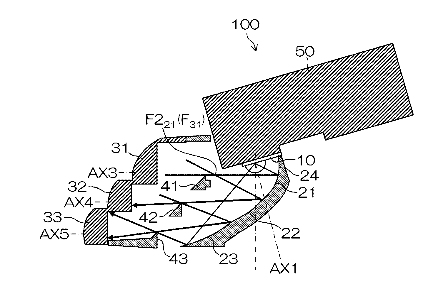
[0068]A description will now be made below to vehicle lights made in accordance with principles of the presently disclosed subject matter with reference to the accompanying drawings in accordance with exemplary embodiments. In the present specification, the directions with regard to the “up,”“down,”“right,”“left,”“front,” and “rear” and the like may be based on the case where the vehicle light is installed in a vehicle body. Namely, the directions may be considered to match to the vertical direction (up-to-down direction), the lateral direction (right-to-left or vehicle width direction), and the front-to-rear direction of the vehicle body.

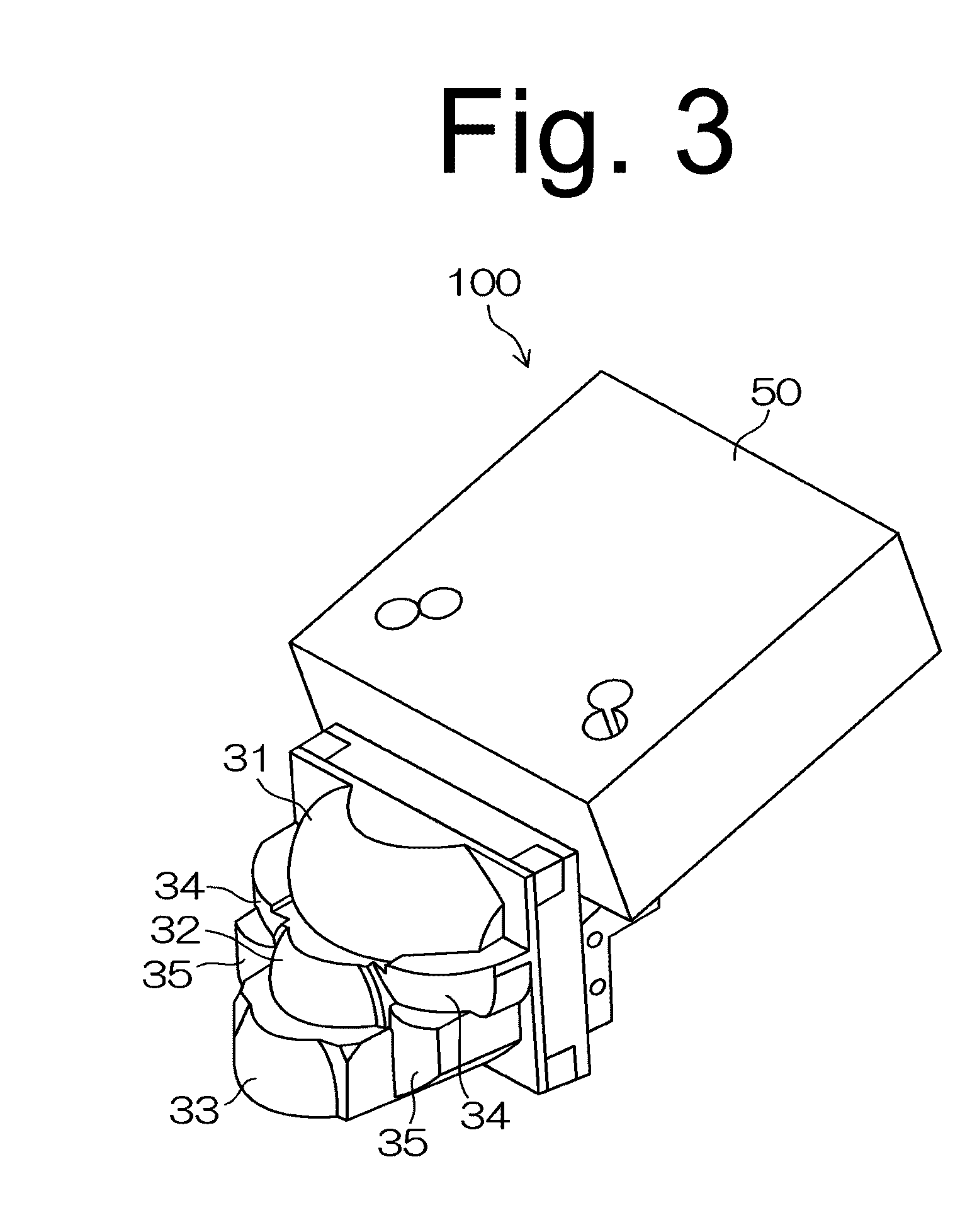
[0069]The vehicle light 100 according to the present exemplary embodiment can be applied to a vehicle headlamp, a vehicle fog lamp or the like for use in a vehicle such as an automobile or the like. FIGS. 3 to 7 show the vehicle light 100. The vehicle light 100 of the present exemplary embodiment can include an LED light source 10, first to fifth r...


PUM


Abstract

A vehicle light can include an LED light source disposed such that the optical axis of the LED light source is directed downward, a first lens disposed forward of the LED light source, a second lens disposed below and forward of the first lens, and a first reflector extending from both sides of the LED light source to a position near the optical axis of the LED light source. The first reflector can be configured to reflect light beams from the LED light source toward the first lens so as to form a wide vertically converged and horizontally diffused light distribution pattern. The vehicle light can include a second reflector disposed at a position below and forward of the first reflector. The second reflector can be configured to reflect light beams from the LED light source toward the second lens so as to form a middle-area vertically converged and horizontally diffused light distribution pattern. The lens can be formed by a toroidal lens that is horizontally elongated and that is formed by horizontally extending an aspherical lens cross section having a focus near the LED light source in an arc shape, or by a cylindrical lens having a horizontal focus line. In particular, the lens can be formed by an upper-half lens portion of such a toroidal lens. The vehicle light can include a light shielding shutter having a first upper edge portion and a second upper edge portion lower than the first upper edge portion.

Description

[0001]This application claims the priority benefit under 35 U.S.C. §119 of Japanese Patent Applications No. 2009-259176 filed on Nov. 12, 2009, No. 2009-260109 filed on Nov. 13, 2009, and No. 2009-260110 filed on Nov. 13, 2009, which are hereby incorporated in their entirety by reference.TECHNICAL FIELD[0002]The presently disclosed subject matter relates to a vehicle light, and in particular, to a vehicle light with reduced number of components. Furthermore, the presently disclosed subject matter relates to a vehicle light that can utilize a lens such as a toroidal lens or a cylindrical lens with a characteristic shape so that “glare light”, that may occur when light beams are directed above a horizontal line H-H and near the opposite vehicle side of the road, can be prevented or suppressed. Still further, the presently disclosed subject matter relates to a vehicle light that can prevent or suppress the generation of partially colored light distribution (in particular, blue colored)...

Claims


Application Information

Patent Timeline
Patent Type & Authority Patents(United States)
IPC IPC(8): F21V7/00F21V19/00F21W107/10
CPCF21S48/1159F21S48/1163F21S48/1233F21S48/1266F21S48/1275F21S48/1388F21W2101/10F21Y2101/02F21Y2115/10F21S41/147F21S41/255F21S41/26F21S41/321F21S41/36F21S41/365F21S41/43F21S45/47F21W2102/135F21W2102/18F21W2102/30F21W2102/00
Inventor FUTAMI, TAKASHI
Owner STANLEY ELECTRIC CO LTD
Why Eureka
Try Eureka