Steering apparatus

a technology of steering apparatus and steering column, which is applied in the direction of steering column, steering parts, vehicle components, etc., can solve the problems of difficult to absorb impacts during contact at the front and rear ends in the sliding direction, easy to lose sliding ability, and difficult to absorb sliding impacts, etc., to achieve improved steering operation feeling and reliable absorbance

Active Publication Date: 2013-09-03
YAMADA MANUFACTURING CO LTD
View PDF15 Cites 8 Cited by
  • Summary
  • Abstract
  • Description
  • Claims
  • Application Information

AI Technical Summary

Benefits of technology

[0007]In the configuration described in Japanese Patent No. 3754075, a locking member 30 is formed as a solid rubber molded on a metal mold or a rubber molding portion having a rubber, so as to provide a buffer portion 31. In the locking member 30 that is inserted into the friction-reducing elements IV′ and IL′ having a frame-like shape, the contact zone is from a rubber. Therefore, an intimate contact state is assumed in elastic contact and sliding ability can be lost. In the configuration described in Japanese Patent Application Laid-Open No. 2000-344112, the sliding is facilitated with respect to that in the configuration described in Japanese Patent No. 3754075 because the resin slider 17 is caused to slide against the resin guides 16a, 16b of the resin frame. However, impacts during contact at the front and rear ends in the sliding direction are difficult to absorb. It is an object of the present invention to improve the smoothness of sliding of a steering column in the telescopic direction, inhibit impacts during the movement of the steering column to the front end and rear end, and improve the operation feeling during steering.
[0010]According to an exemplary embodiment of the invention, the end edges in the up-down direction of the long hole for telescopic adjustment are taken as guided edges, and only the upper and lower sliding surfaces of the sliding main body portion, which is made from an inelastic resin, of the sliding shaft support member are in contact with the upper and lower guide edges, whereas the buffer portions made from an elastic resin are not in contact with the guide edges. As a result, good sliding ability of the sliding shaft support member can be obtained. In addition, because the buffer portions made from an elastic resin are fixedly attached in the front-rear direction of the long hole for telescopic adjustment, a structure is obtained such that when the sliding shaft support member moves reciprocatingly in the front-rear direction of the long hole for telescopic adjustment, the buffer portions abut against the stop end edges, the impact occurring at the instant the buffer portions and stop end edges abut against each other is inhibited, the impact noise is minimized, and extremely good operation feeling during telescopic adjustment can be obtained.
[0012]Further, the two sides in the front-rear direction of the main sliding unit are contactless region portions. With such a configuration, by taking the contactless region portions of the main sliding unit as reference planes for dimensions in the up-down direction in resin formation when the buffer portions are formed and fixedly attached, it is possible to form easily the buffer portions that are not in contact with the two guide edges of the long hole for telescopic adjustment by merely conducting resin molding so that the two end surfaces of the buffer portions in the up-down direction are flush. Further, the structure of the sliding shaft support member can be simplified. In addition, since contactless region portions are formed in the sliding main body portion, there are portions that are not in contact with the upper and lower guide edges of the long hole for telescopic adjustment, the contact surface area is reduced, and therefore sliding ability is improved.
[0013]Furthermore, in additional exemplary embodiments of the invention, a recess of a substantially bifurcated shape is formed in the sliding shaft support portion, a through hole that passes through in the up-down direction is formed in the bifurcated section of the main sliding unit in a position corresponding to a zone where the recess is formed, and a shaft-like portion is integrally formed in the up-down direction of the recess. Further, part of the buffer portion is inserted into the recess and fixedly attached thereto, whereby the volume ratio of buffer portions in the sliding shaft support member increases and impact absorption ability increases.
[0015]The protruding portion and the shaft-like portion formed at the main sliding unit side produce a synergetic effect and the buffer portion can play a role of a pull-out stop from the sliding main body portion, impacts can be reliably absorbed and a durable sliding shaft support member can be obtained. Sliding of the steering column in the telescopic direction is thus made smoother, impacts during movement towards the front end and rear end side of the steering column can be inhibited, and the operation feeling of steering can be improved.

Problems solved by technology

Therefore, an intimate contact state is assumed in elastic contact and sliding ability can be lost.
However, impacts during contact at the front and rear ends in the sliding direction are difficult to absorb.

Method used


Image

  • Steering apparatus
  • Steering apparatus
  • Steering apparatus

Examples


second embodiment

[0044]Further, in the sliding shaft support member A, the attachment structure of the buffer portion 6 to the main sliding unit 5 is obtained by forming only the contact region portion 51, contactless region portion 52, and recess 53 in the main sliding unit 5 and fixedly attaching the buffer portion 6 to the recess 53 (see FIG. 8A). In this case, only the buffer portions 6 are molded in the mold and the insertion piece 61 of the buffer portion 6 is inserted into the recess 53 of the main sliding unit 5.

third embodiment

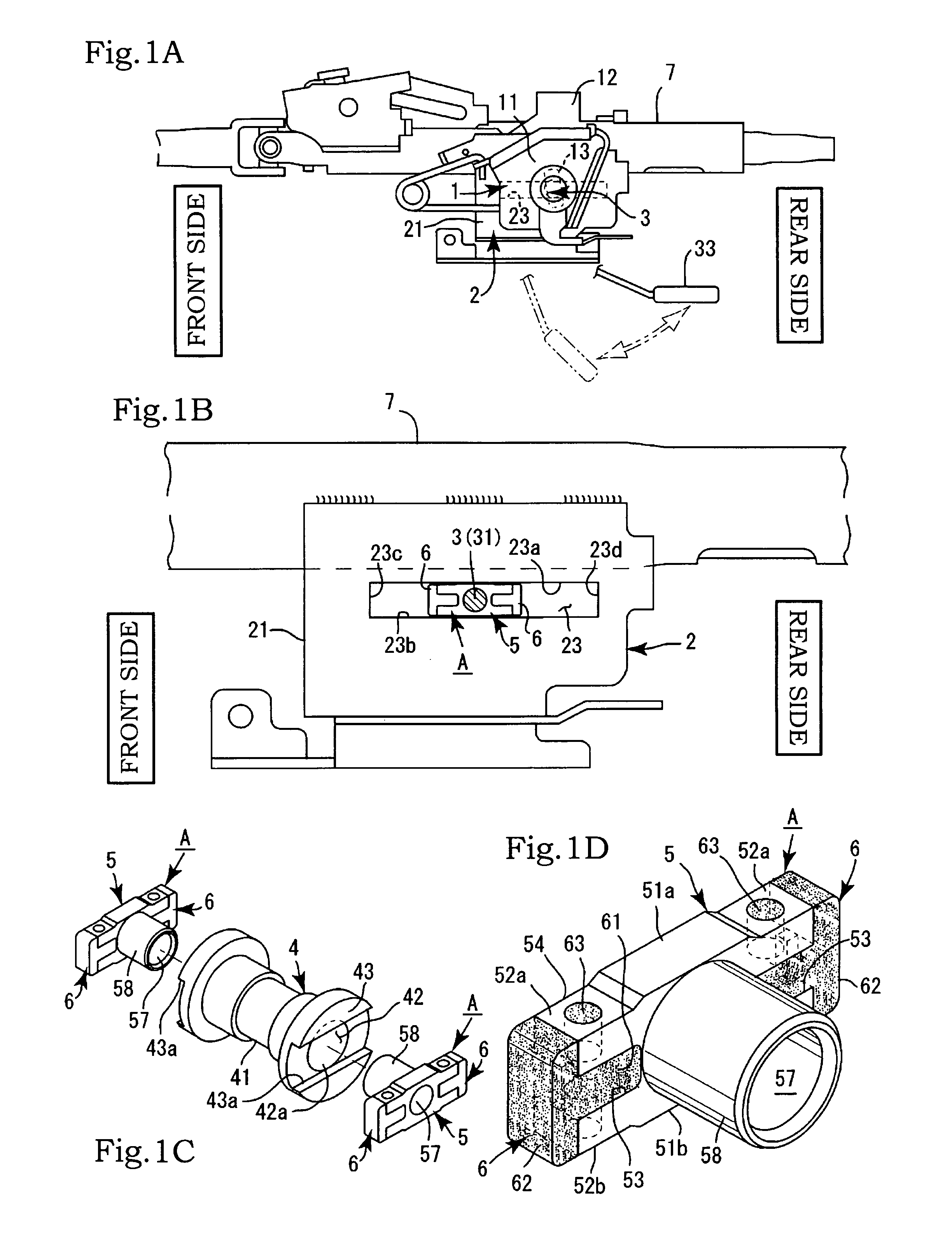
[0045]Further, the main sliding unit 5 and buffer portion 6 can be also joined by a dovetail joint structure. Thus, in such a configuration, a mortise 59 is formed in the main sliding unit 5, a tenon 64 that will be locked in the mortise 59 is formed in the buffer portion 6, and the tenon 64 of the buffer portion 6 is locked in and joined with the mortise 59 of the main sliding unit 5 (see FIGS. 8A and 8B). In the sliding shaft support member A, the upper sliding surface 51a and lower sliding surface 51b are provided over the entire upper and lower surfaces in the main sliding unit 5 and no contactless region portion 52 is formed in the main sliding unit 5 (see FIGS. 8C and 8D).

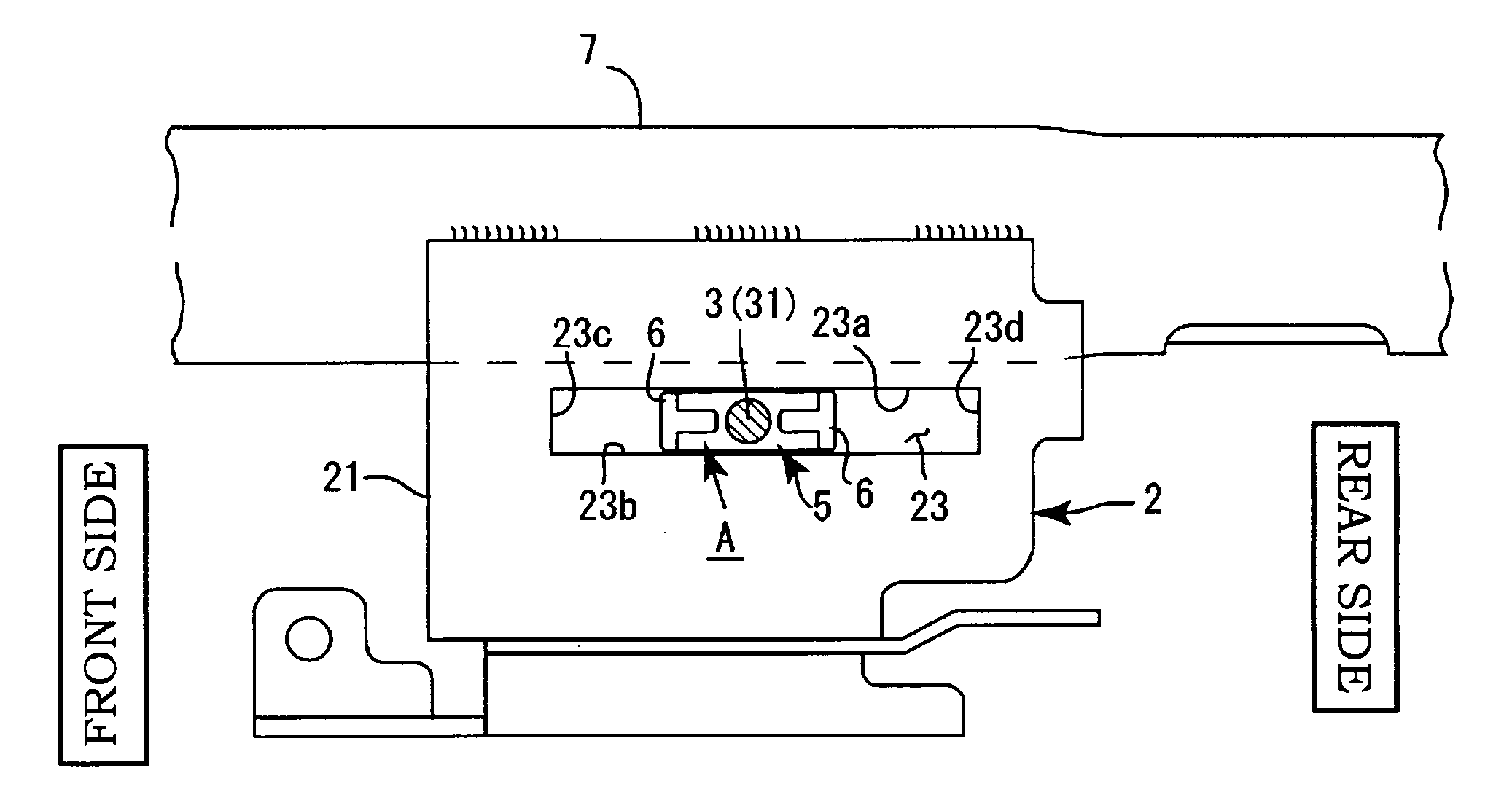
[0046]The configuration of the steering apparatus in accordance with the present invention will be explained below. The main sliding unit 5 and buffer portions 6 of the sliding shaft support member A are inserted into and mounted on the long hole 23 for telescopic adjustment. The upper sliding surface 51a and...


PUM


Abstract

The present invention provides a steering apparatus that can provide good operation feeling in telescopic adjustment and can have a very simple configuration. The steering apparatus has a fixed bracket, a movable bracket, a sliding shaft support member, and a tightening tool. The sliding shaft support member is constituted by a main sliding unit made of an inelastic resin and buffer portions made of a rubber or an elastic resin. The buffer portions are fixedly attached to both sides of the main sliding unit in the front-rear direction, the upper and lower surfaces of the main sliding unit are in a state of sliding contact with both guide edges of a long hole for telescopic adjustment of the movable bracket, and the buffer portions can abut only on both stop end edges and do not come into contact with the two guide edges.

Description

BACKGROUND OF THE INVENTION[0001]1. Field of the Invention[0002]The present invention relates to a steering apparatus that can provide good operation feeling in telescopic adjustment and can have a very simple configuration.[0003]2. Description of the Related Art[0004]There are steering apparatuses provided with a telescopic adjustment mechanism. A typical structure of the steering apparatus of this kind is constituted by a fixed bracket mounted on a vehicle and a movable bracket provided with the steering column, and the movable bracket is mounted on the fixed bracket so that the movable bracket can move in the front-rear direction and can be fixed. The fixed bracket is typically configured to clamp the movable bracket. The sliding movement of the movable bracket in the front-rear direction is realized by a long hole for telescopic operation that is present in either of the movable bracket and fixed bracket, a bolt inserted into the long hole for telescopic operation, a tightening ...

Claims


Application Information

Patent Timeline
Patent Type & Authority Patents(United States)
IPC IPC(8): B62D1/18
CPCB62D1/184B62D1/185
Inventor HIROOKA, KOUJISUGISHITA, SUGURU
Owner YAMADA MANUFACTURING CO LTD
Why Eureka
Try Eureka