Connector

a technology of connecting rods and connectors, applied in the direction of connecting devices, propulsion by batteries/cells, transportation and packaging, etc., can solve the problems of increasing the number of parts and the size of the entire connection structure, and achieve the effect of preventing the position of the insulating member, facilitating the operation of the connection, and facilitating the downsizing of the connector

Inactive Publication Date: 2013-09-03
HITACHI CABLE
View PDF24 Cites 9 Cited by
  • Summary
  • Abstract
  • Description
  • Claims
  • Application Information

AI Technical Summary

Benefits of technology

[0035]According to one embodiment of the invention, a connector is provided with an insulating member assembly assembled such that insulating members (which compose the insulating member assembly) are restricted from moving in a fitting direction and a width direction thereof (i.e., these directions being perpendicular to each other) by connecting the insulating members as engaged to each other. Accordingly, it is possible to prevent the position of the insulating members from being misaligned even when a force (e.g., a force to pull or push a cable connected with the connector) is applied to the cable. As a result, when two connector portions of the connector are fitted to each other, second connecting terminals (to be inserted between the insulating members) can be prevented from butting to the insulating members so as to smooth the fitting operation. Moreover, the connector can be downsized since the embodiment of the invention can omit the retaining jig unlike the conventional connector by using the insulating member assembly thus assembled.

Problems solved by technology

(1) There is a problem that the number of parts increases since a retaining jig for holding one end of each insulating member is provided as a separate member.
(2) Since the retaining jig for holding one end of each insulating member is a separate member, another problem arises that a connection portion between the retaining jig and the insulating member becomes large, so that the entire connection structure becomes large.

Method used


Image

  • Connector
  • Connector
  • Connector

Examples


Embodiment Construction

[0044]A preferred embodiment of the invention will be described below in conjunction with the appended drawings.

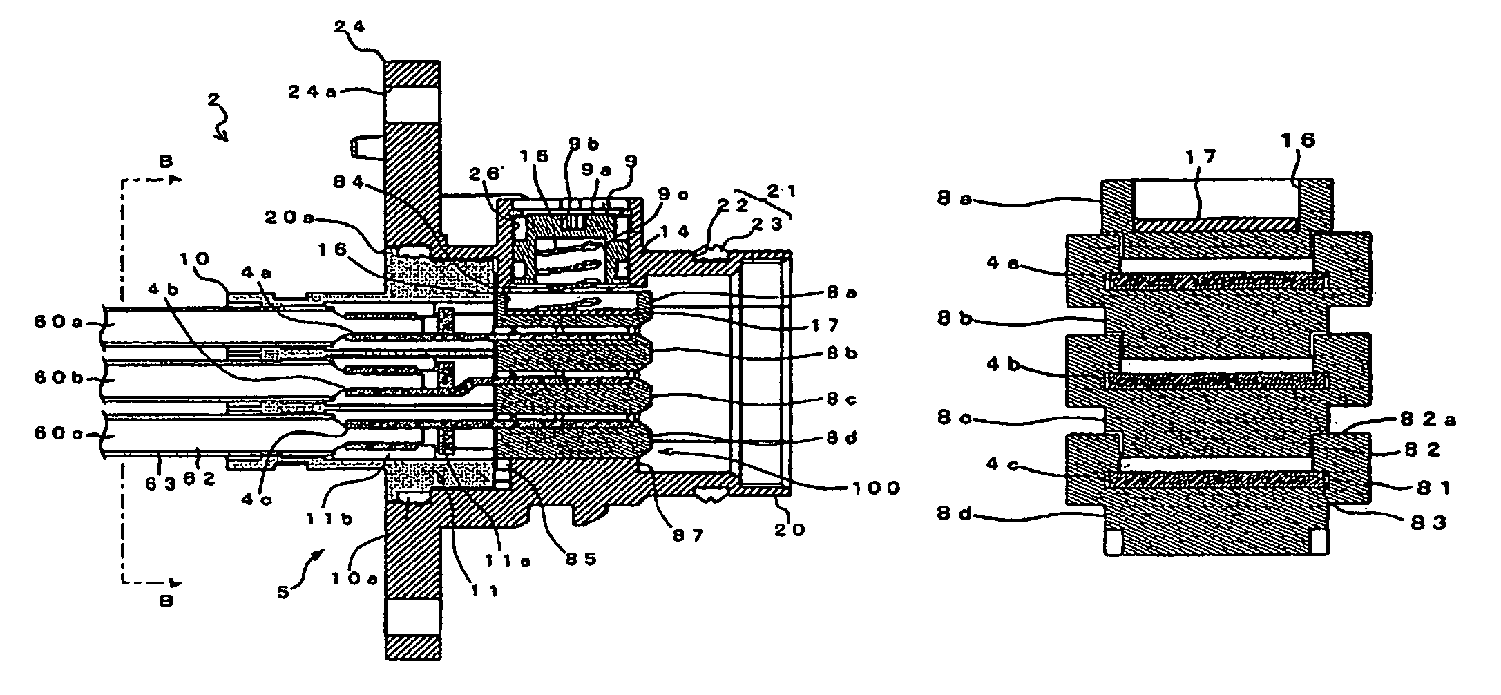
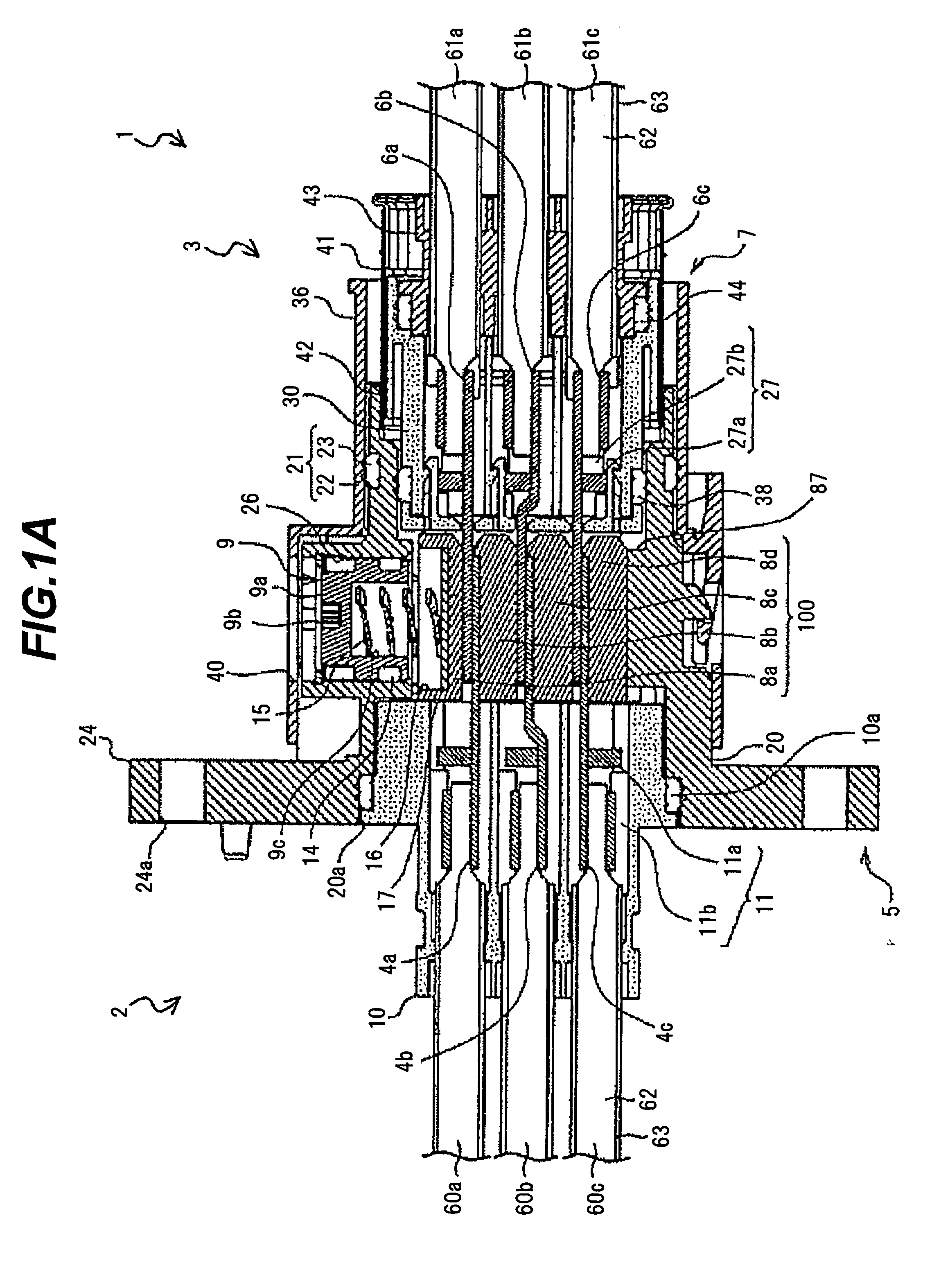
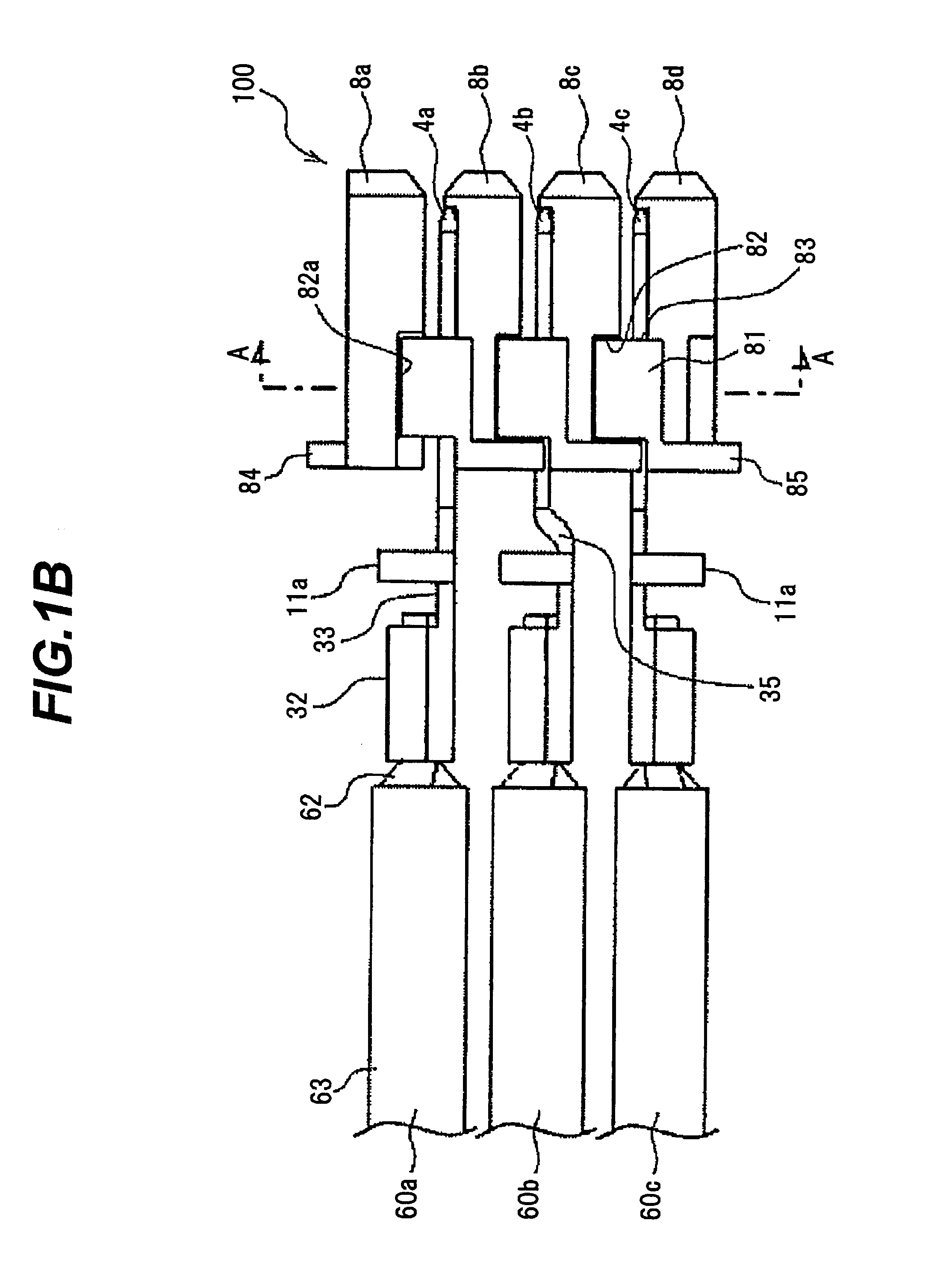
[0045]FIGS. 1A, 1B, 2A and 2B are diagrams illustrating a connector in an embodiment, wherein FIG. 1A is a cross sectional view, FIG. 1B is a side view showing first connecting terminals and an insulating member assembly, FIG. 2A is a perspective view and FIG. 2B is a plan view.

[0046]As shown in FIGS. 1A, 1B, 2A and 2B, a connector 1 of the present embodiment is composed of a first connector portion 2 and a second connector portion 3, and plural power lines are connected at a time by fitting the connector portions 2 and 3 together.

[0047]More specifically, the connector 1 is provided with the first connector portion 2 having a first terminal housing (i.e., male terminal housing) 5 housing plural (three) aligned first connecting terminals (i.e., male terminals) 4a to 4c, the second connector portion 3 having a second terminal housing (i.e., female terminal housing) 7 housing...


PUM


Abstract

A connector includes a first terminal housing for housing a plurality of first connecting terminals aligned, a second terminal housing for housing a plurality of second connecting terminals aligned, a plurality of insulating members that are aligned and housed in the first terminal housing, a connecting member for collectively fixing and electrically connecting the plurality of first connecting terminals and the plurality of second connecting terminals at each contact point by pressing one of the plurality of insulating members adjacent to the connecting member, and an insulating member assembly including the plurality of insulating members assembled such that the plurality of insulating members are each restricted from moving in a fitting direction thereof, and moving in a width direction perpendicular to a lamination direction of the laminated structure and to the fitting direction.

Description

[0001]The present application is based on Japanese patent application No. 2010-284737 filed on Dec. 21, 2010, the entire contents of which are incorporated herein by reference.BACKGROUND OF THE INVENTION[0002]1. Field of the Invention[0003]The invention relates to a connector used for, e.g., an eco-friendly car such as a hybrid car and an electric car and, in particular, to a connector that may be used for a power harness for transmitting a large amount of power.[0004]2. Description of the Related Art[0005]A power harness is used for connecting between devices such as between a motor and an inverter or between an inverter and a battery in, e.g., a hybrid car or an electric car, which has made significant progress in recent years, for transmitting a large amount of power, and a connector in a two-divided structure composed of, e.g., a male connector portion provided with a male terminal as well as a first terminal housing for housing the male terminal and a female connector portion p...

Claims


Application Information

Patent Timeline
Patent Type & Authority Patents(United States)
IPC IPC(8): H01R13/15
CPCB60L11/1803H01R13/193H01R13/26H01R13/639H01R24/62B60L2240/36H01R2107/00H01R2201/26Y02T10/7005B60L50/51Y02T10/70
Inventor SUZUKI, SACHIOTAKEHARA, HIDEAKIFUKUDA, KUNIHIROKATAOKA, YUTAUMETSU, JUNHAYASHI, SHINYA
Owner HITACHI CABLE
Why Eureka
Try Eureka