Self watering plant system

a plant system and self-watering technology, applied in the field of self-watering plant systems, can solve the problems of uncontrollable water running into the soil, most plants do not adequately regulate the amount of water given to them, etc., and achieve the effect of reducing the large fluctuation in soil moistur

Inactive Publication Date: 2013-09-10
GRIEBEL ARTHUR FRANCIS
View PDF34 Cites 11 Cited by
  • Summary
  • Abstract
  • Description
  • Claims
  • Application Information

AI Technical Summary

Benefits of technology

[0003]It is an object of this invention to eliminate the large fluctuation in soil moisture that is seen in both wicks systems and non self-watering planters.
[0004]Another object of this invention is to use a simple design that is easy to use and to manufacture.
[0005]The objects of this invention are achieved by incorporating certain features from wick systems and vacuum systems in a way that eliminates the problems that are seen in both. A vacuum-sealed reservoir is used to suspend liquid so that it does not freely flow into the soil. A wick is used so that the water in the reservoir does not have direct contact with the soil, preventing soil saturation. The lower end of the wick is inside the reservoir. The middle section of the wick is also inside the reservoir, but is walled inside the wick housing, creating a buffer between the liquid in the reservoir and the soil. Water can only enter the middle section when the vacuum seal is broken. The top section of the wick is contained in the soil.

Problems solved by technology

Several self-water planters and devices exist, but most do not adequately regulate the amount of water that is given to a plant.
Several self-water planters operate based on a vacuum, but they tend to lead to overwatering.
When the filling lid is removed to fill the reservoir, water runs uncontrollable into the soil.

Method used


Image

  • Self watering plant system
  • Self watering plant system
  • Self watering plant system

Examples


Embodiment Construction

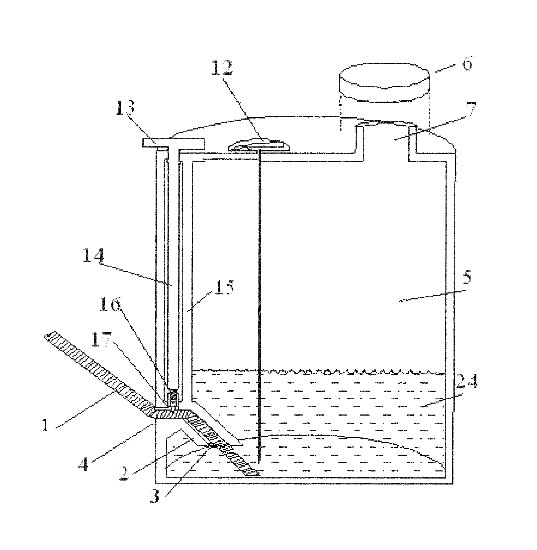
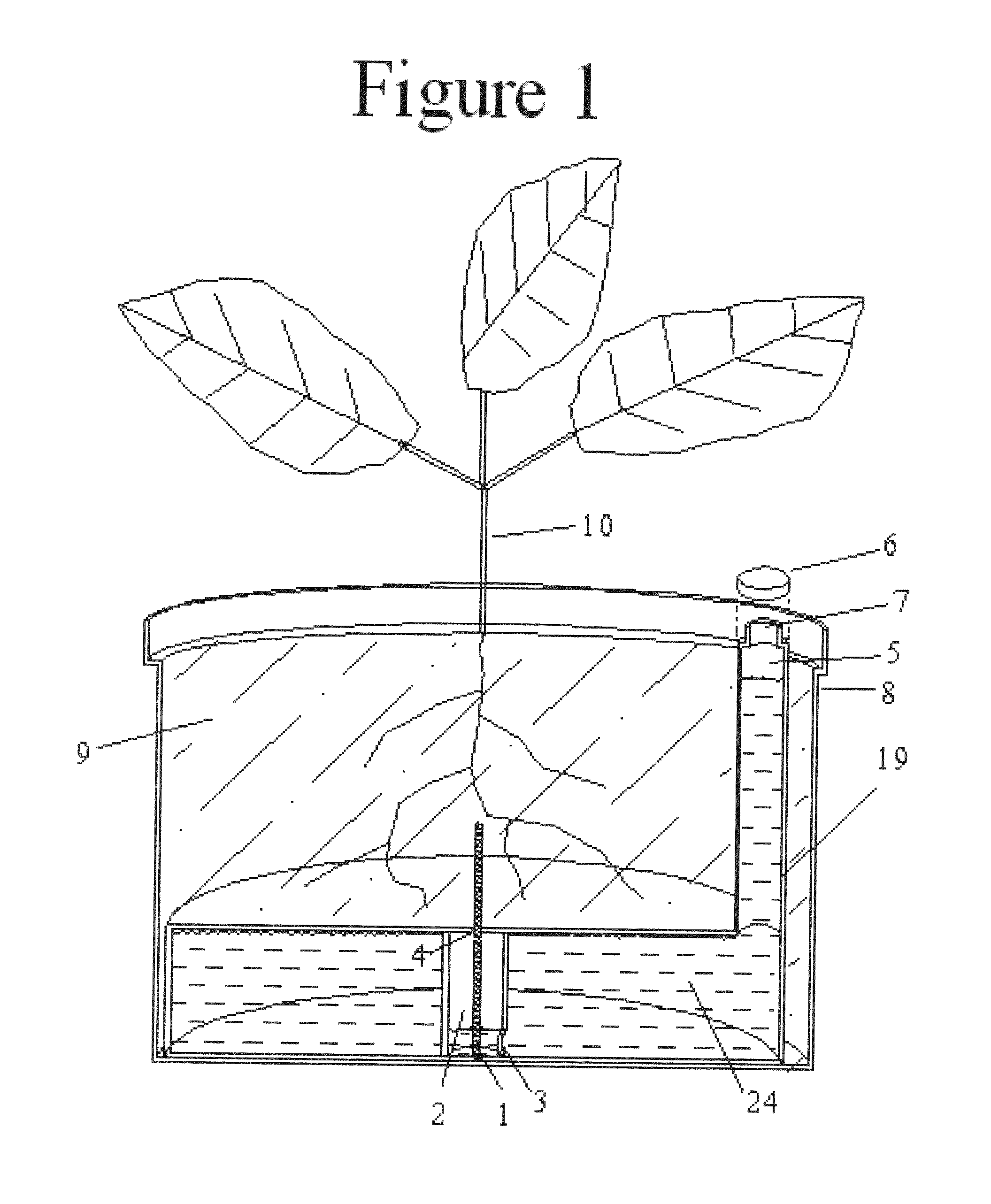
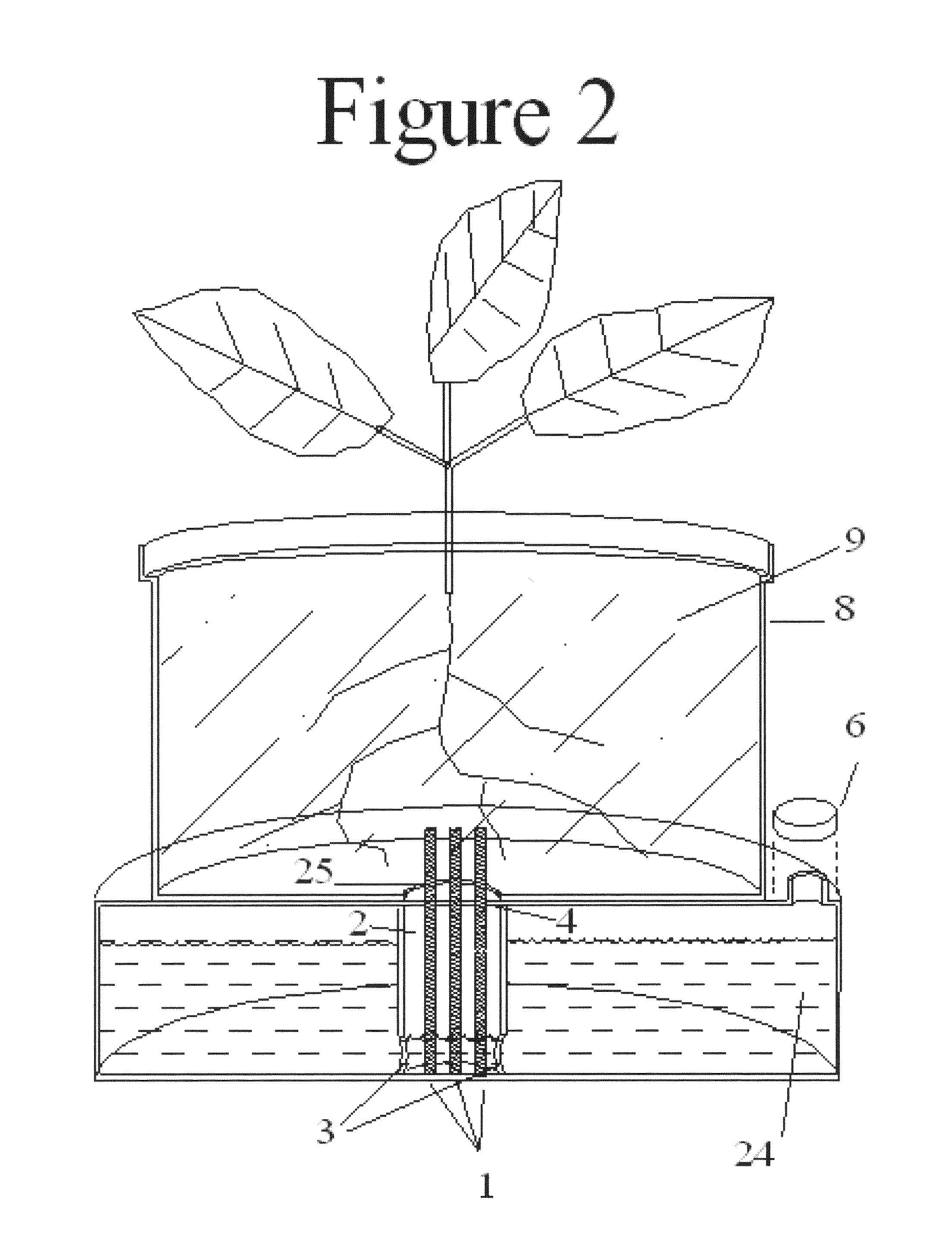
[0016]In FIG. 1, a cross sectional view, the invention is shown in an embodiment that is inserted into any standard plant pot 8. The cap 6 is removed to pour liquid 24 through the spout 7, filling the reservoir 5. During filling, water is restricted from flowing freely into the soil 9 by the diameter of the hole 4 at the top of the wick housing 2. The hole 4 should be snug around the wick 1 so that liquid 24 must flow through the wick 1 to enter the soil 9. The hole 4 should not be so tight as to pinch off the flow of liquid 24. Since the wick 1 remains wet, organic materials such as cotton is would be prone to rot. For this reason, a non-organic material is recommended for the wick 1.

[0017]When the reservoir is full and the cap 6 is used to close the spout 7, a vacuum is created and liquid 24 cannot leave the reservoir until the vacuum is broken. In order to create the vacuum, the body of the reservoir 19 must be made of a non-porous material. Also, the cap 6 must make a tight seal...


PUM


Abstract

This Self-Watering Planter comprises a wick, reservoir, wick-housing running between the soil / soil substitute and the reservoir, and a tight fitting cap to maintain a vacuum seal within the reservoir. The water or liquid mixture is maintained at a constant level across the wick by the vacuum that is created. This prevents water from flowing upwards into the soil when the soil is already wet. Liquid is only draw from the wick by osmosis when the soil is dry. Even as the water level in the reservoir drops, the water level across the wick continues to remain level until the reservoir is nearly empty, allowing the soil constant access to water until the reservoir needs refilling. Several embodiments are included. All contains these features, but some contain addition features as well as different proportions. The uses of the different embodiments are also described.

Description

BACKGROUND OF THE INVENTION[0001]Non-self watering planters often require daily attention to check soil moisture and water as needed. If is also common for under and overwater to occur when the plants are not checked often enough of if too much water is given.[0002]Several self-water planters and devices exist, but most do not adequately regulate the amount of water that is given to a plant. Wick systems tend to allow the soil to remain very wet when the reservoir is full and dry when the liquid in the reservoir runs low. Several self-water planters operate based on a vacuum, but they tend to lead to overwatering. When the filling lid is removed to fill the reservoir, water runs uncontrollable into the soil. Also typically, they rely on soil saturation to stop the flow of water.SUMMARY OF THE INVENTION[0003]It is an object of this invention to eliminate the large fluctuation in soil moisture that is seen in both wicks systems and non self-watering planters.[0004]Another object of th...

Claims


Application Information

Patent Timeline
Patent Type & Authority Patents(United States)
IPC IPC(8): A01G27/06
CPCA01G27/06
Inventor GRIEBEL, ARTHUR FRANCIS
Owner GRIEBEL ARTHUR FRANCIS
Why Eureka
Try Eureka