Ratchet buckle

a ratchet buckle and buckle technology, applied in the field of ratchet buckles, can solve the problems that the strap cannot be quickly withdrawn or collected, and achieve the effect of no shearing force and easy reeling of the strap

Inactive Publication Date: 2013-09-10
WIN CHANCE METAL
View PDF10 Cites 4 Cited by
  • Summary
  • Abstract
  • Description
  • Claims
  • Application Information

AI Technical Summary

Benefits of technology

[0008]A main objective of the present invention is to provide a ratchet buckle that has no shearing force and easily reels straps.
[0016]a positioning rod transversally attached to the first end of the trigger and engaged to the two positioning notches of the body to locate the relative position of the body and the trigger to keep the two pivotal holes of the body and the two shaft holes of the trigger concentric and thus to keep the pivotal shaft of the body from being pressed by shearing force to rotate easily;

Problems solved by technology

Therefore, the straps cannot be rapidly withdrawn or collected.

Method used


Image

  • Ratchet buckle
  • Ratchet buckle
  • Ratchet buckle

Examples


Embodiment Construction

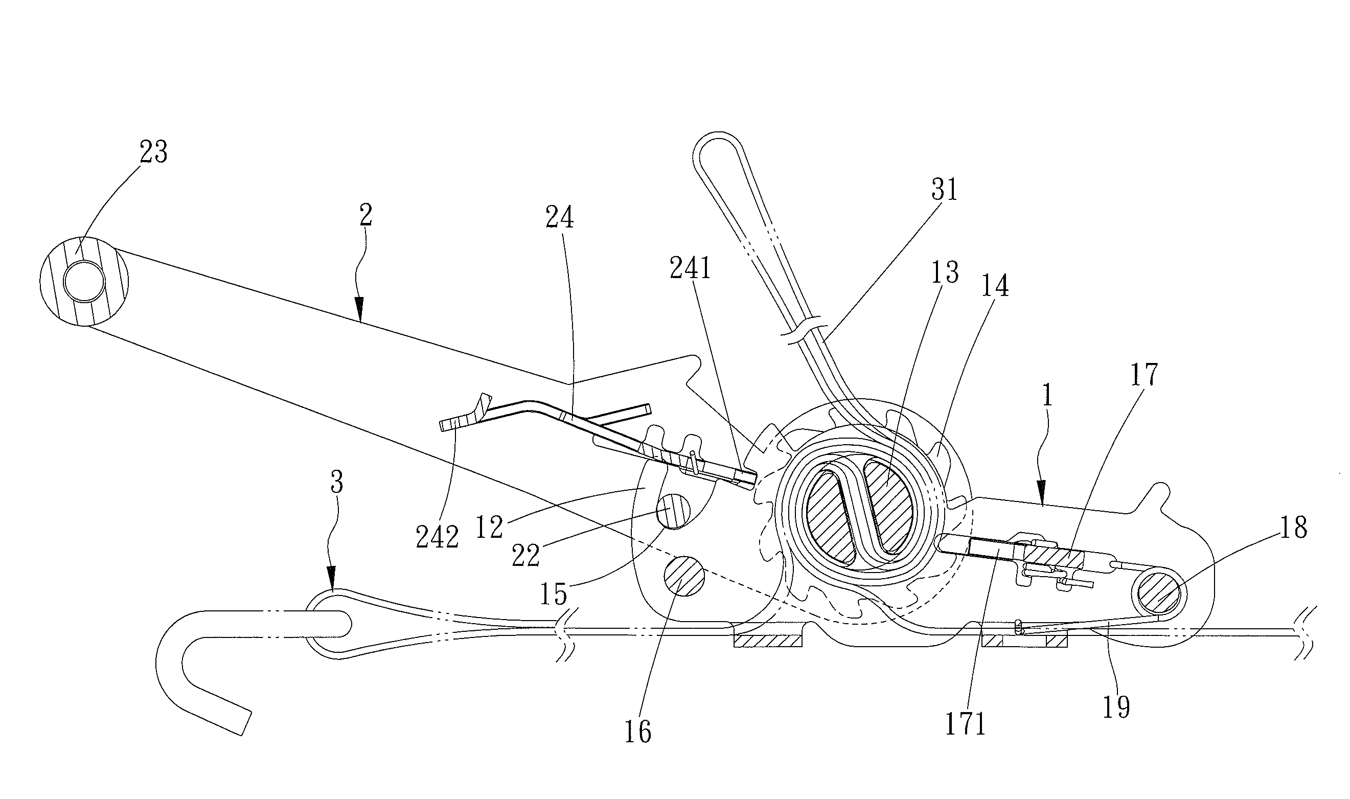
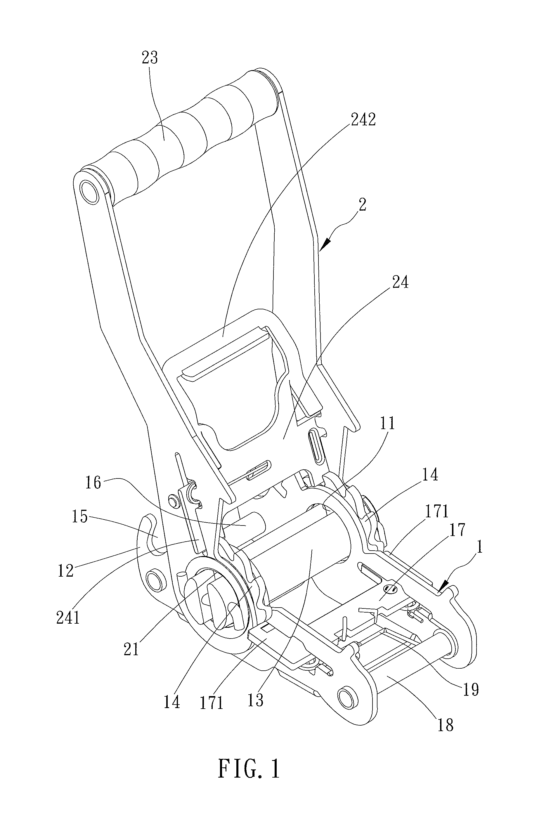
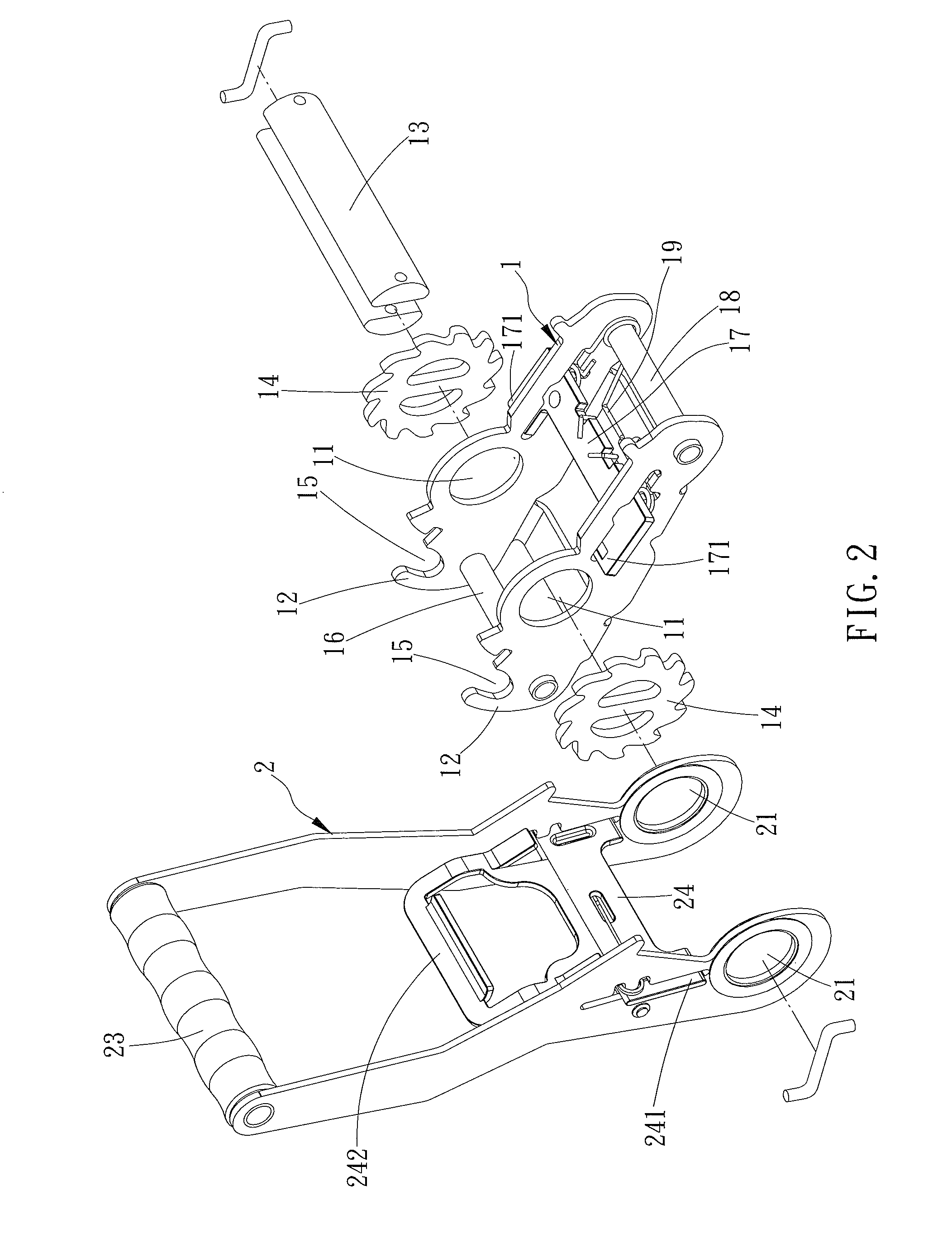
[0029]A ratchet buckle in accordance with the present invention comprises a body and a trigger. One end of the body has two opposite pivotal holes, two opposite positioning notches, and a pivotal shaft penetrating the pivotal holes. Two ends of the pivotal shaft each have a ratchet wheel synchronously rotating with the pivotal shaft. One end of the trigger has two opposite shaft holes engaged to the pivotal shaft of the body and has a positioning rod transversally mounted on the trigger to engage the two positioning notches of the body. By operating the trigger to set the pivotal shaft free, the pivotal shaft is easily rotated to reel a strap.

[0030]As shown in FIGS. 1 to 4, a preferred embodiment of a ratchet buckle in accordance with the present invention comprises a body 1 and a trigger 2. The body 1 has a first end and a second end. The first end of the body 1 has two opposite pivotal holes 11 and two opposite extension portions 12. The two pivotal holes 11 are penetrated by a pi...


PUM

PropertyMeasurementUnit
shearing forceaaaaaaaaaa
distanceaaaaaaaaaa
resistanceaaaaaaaaaa

Abstract

A ratchet buckle has a body and a trigger. One end of the body has two opposite pivotal holes, two opposite positioning notches, and a pivotal shaft penetrating the pivotal holes. Two ends of the pivotal shaft each have a ratchet wheel synchronously rotating with the pivotal shaft. One end of the trigger has two opposite shaft holes engaged to the pivotal shaft of the body and has a positioning rod transversally mounted on the trigger to engage the two positioning notches of the body. By operating the trigger to set the pivotal shaft free, the pivotal shaft is easily rotated to reel a strap.

Description

BACKGROUND OF THE INVENTION[0001]1. Field of the Invention[0002]The present invention relates to a ratchet buckle and, more particularly, to a ratchet buckle that easily reels a strap without resistance.[0003]2. Description of Related Art[0004]In the transportation operation of general goods, racks will be located on vehicles to limit movement of the goods, and straps will tie up the racks to ensure the stability of the goods. The tightening of the straps is made by hooks at ends of the straps hooking at two sides of a track frame and fastened by ratchet buckles.[0005]As shown in FIGS. 8 and 9, a conventional ratchet buckle comprises a body 6 and a trigger 7. The body 6 has a first end and a second end. The first end of the body 6 has two pivotal holes 61 formed oppositely to pivotally engage a pivotal shaft 62, which is mounted with a reel of strap. Two ratchet wheels 63 sleeve on the pivotal shaft 62 on inner sides of the two pivotal holes 61 respectively. The second end has a fix...

Claims


Application Information

Patent Timeline
Patent Type & Authority Patents(United States)
IPC IPC(8): B65H75/38
CPCB60P7/083Y10T24/2175
Inventor CHANG, WEN CHENG
Owner WIN CHANCE METAL
Why Eureka
Try Eureka