System and method for turbine compartment ventilation

a technology for ventilation fans and turbine compartments, applied in machines/engines, liquid fuel engines, light and heating apparatus, etc., can solve the problems of increased parasitic electricity consumption of ventilation fans, non-uniform cooling, and difficult ventilation design

Active Publication Date: 2013-09-10
GENERAL ELECTRIC CO
View PDF4 Cites 30 Cited by
  • Summary
  • Abstract
  • Description
  • Claims
  • Application Information

AI Technical Summary

Problems solved by technology

These factors may make ventilation designs challenging for sites that experience extreme ambient air temperatures above 120 degrees Fahrenheit.
However, increased ventilation air flow can cause problems due to non-uniform cooling, increased parasitic electricity consumption by the ventilation fans, low sensitivity of VOC leakage detection, as well as increased leakage in compartment doors.

Method used


Image

  • System and method for turbine compartment ventilation
  • System and method for turbine compartment ventilation
  • System and method for turbine compartment ventilation

Examples


Embodiment Construction

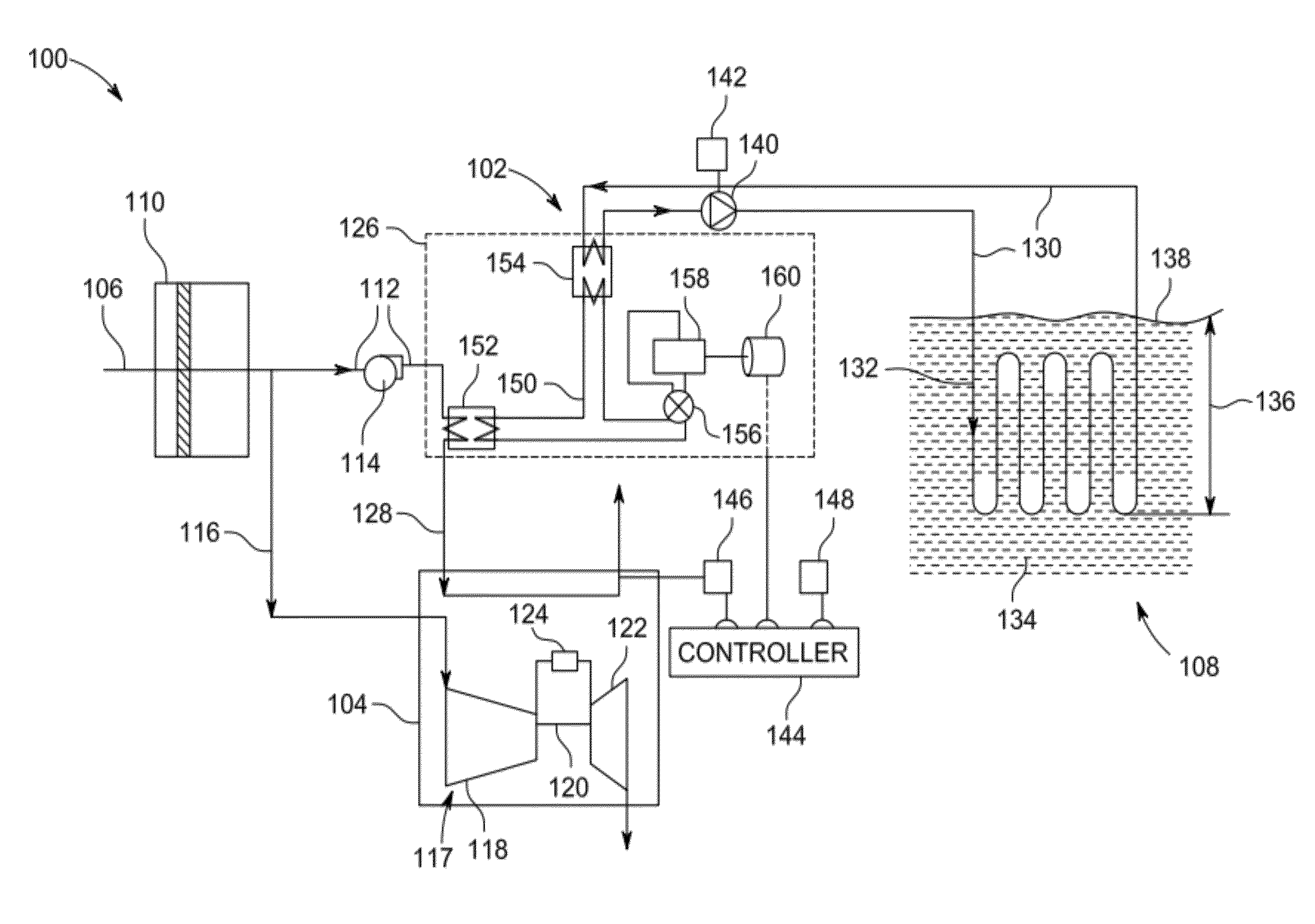
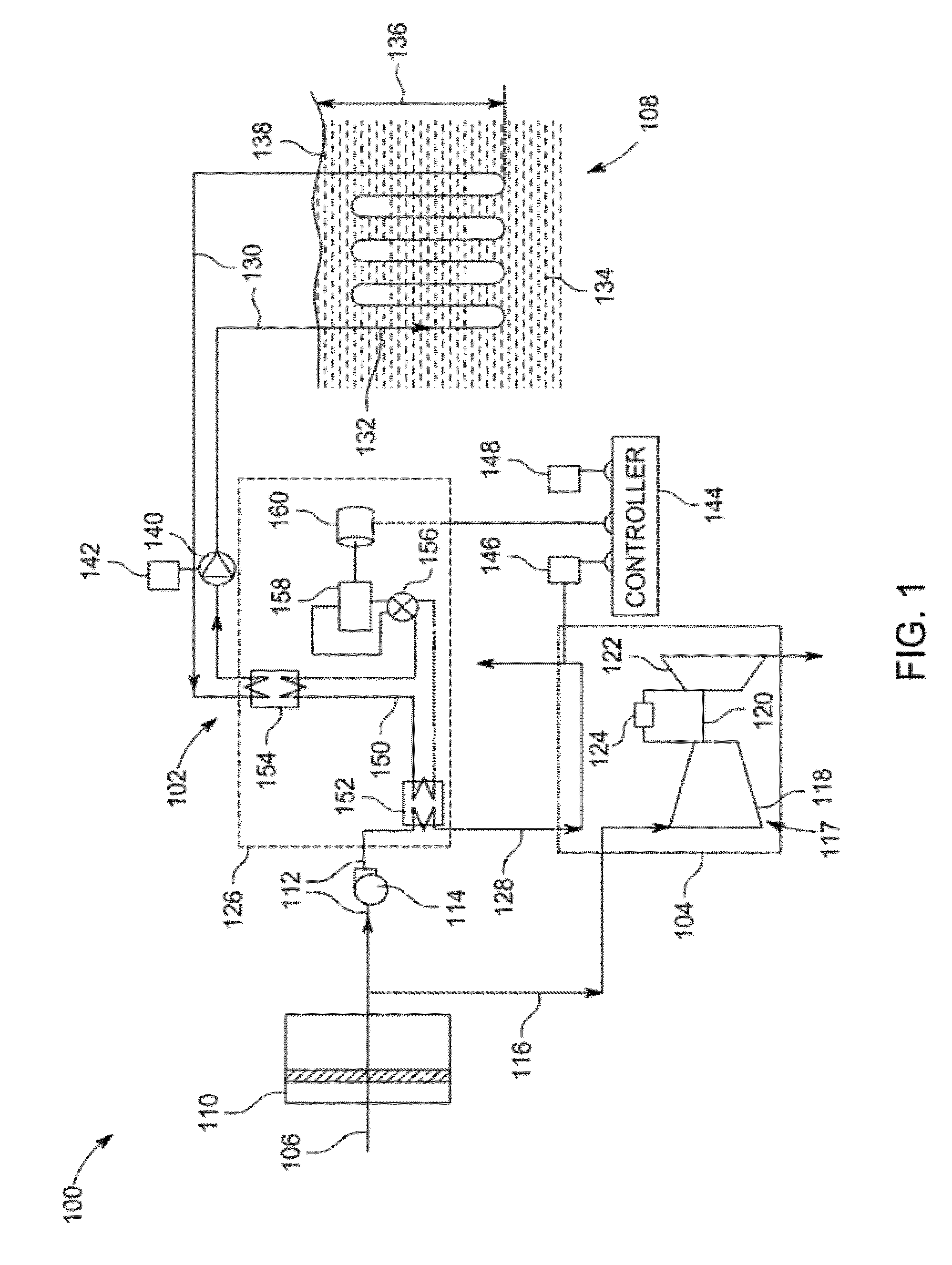
[0011]FIG. 1 shows a schematic diagram of an embodiment of a power generation system 100 used to generate an electrical and / or mechanical power output. The power generation system 100 includes a ventilation system 102 and turbine compartment 104. The ventilation system 102 is configured to condition an air intake 106 to turbine compartment 104. As depicted, the ventilation system 102 includes and utilizes a geothermal system 108 to condition the air. The ambient air intake 106 includes a filter 110 to remove particles and impurities from the external air. The ambient air flow is directed through a first conduit 112, which includes a first vent fan 114 providing a force to cause the air flow through the first conduit 112. In an embodiment, the ambient air intake 106 directs a portion of air flow to the first conduit 112 and a second portion to a turbine air supply 116. The turbine air supply 116 directs an air flow used by the turbine engine 117. The turbine engine 117 includes a com...


PUM


Abstract

According to an aspect of the invention, a method for ventilating a turbine compartment is provided, the method comprising directing an air flow from an air intake to a first air conduit, transferring a first heat between the air flow and a first fluid within a heat exchange apparatus and pumping the first fluid through a fluid circuit in fluid communication with the heat exchange apparatus, wherein a portion of the fluid circuit is located underground. The method further includes transferring a second heat between the first fluid and a surrounding ground and directing a conditioned air flow from the heat exchange apparatus to a turbine compartment via a second air conduit.

Description

BACKGROUND OF THE INVENTION[0001]The subject matter disclosed herein relates to power generation plants. More particularly, the subject matter relates to ventilating a turbine compartment of a power generation plant.[0002]In power generation systems, a turbine compartment needs proper ventilation for several reasons. Examples of turbine compartment ventilation considerations include maintaining turbine clearances within reasonable ranges for better operational efficiency and keeping volatile organic compounds (VOCs) from accumulating inside of the turbine compartment. Ventilation capacity for a gas turbine compartment is determined based on several factors, including turbine casing surface heat dissipation rates, leakage from gas turbine casing flanges, local ambient conditions, ventilation arrangement (such as pressurized or non-pressurized turbine compartment) and safety considerations. These factors may make ventilation designs challenging for sites that experience extreme ambien...

Claims


Application Information

Patent Timeline
Patent Type & Authority Patents(United States)
IPC IPC(8): F01D25/08
CPCF02C7/00F02C7/20F24J3/081F01D25/12F01D25/14F02C7/12F05D2260/605F05D2260/608F24T10/10Y02E10/10
Inventor ZHANG, JIANMIN
Owner GENERAL ELECTRIC CO
Why Eureka
Try Eureka