Remote identification of non-lambertian materials

a technology of material identification and remote sensing, applied in the field of remote sensing and material identification, can solve the problems prone to yield erroneous results or no results, etc., and achieve the effect of reducing the probability of false matches and increasing the probability of correct identification of target materials

Active Publication Date: 2013-09-10
RAYTHEON CO
View PDF1 Cites 17 Cited by
  • Summary
  • Abstract
  • Description
  • Claims
  • Application Information

AI Technical Summary

Benefits of technology

[0010]According to one example of a method for remotely identifying a non-Lambertian target material, a spectral signature for a target is determined from each of at least two different sets of imagery acquired at different angles, and compared to a predicted signature for a candidate material for each of the at least two different angles. The predicted signatures take into account the known anisotropy of reflectance and / or emissivity of the candidate material. If the target material is non-Lambertian, using two angles and predicted spectral signatures for candidates for those two angles tends to increase the probability of correct identification of the target material and tends to decrease the probability of false matches.

Problems solved by technology

Treating all targets as Lambertian in remote material identification processes tends to yield erroneous results or no results at all when remotely identifying non-Lambertian materials using spectral signatures.
If the target material is non-Lambertian, using two angles and predicted spectral signatures for candidates for those two angles tends to increase the probability of correct identification of the target material and tends to decrease the probability of false matches.

Method used


Image

  • Remote identification of non-lambertian materials
  • Remote identification of non-lambertian materials
  • Remote identification of non-lambertian materials

Examples


Embodiment Construction

[0028]In the following description, like numbers refer to like elements.

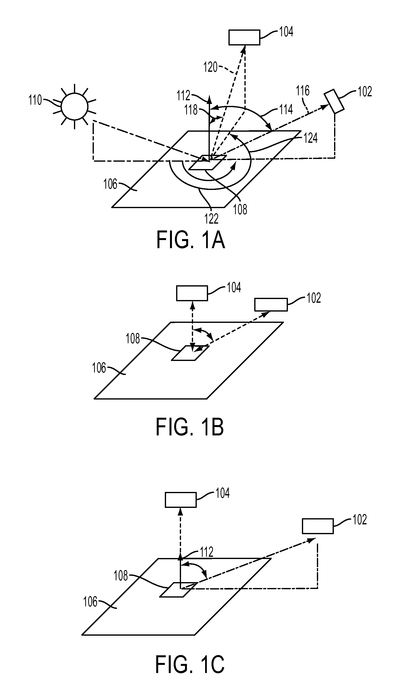
[0029]Referring to FIGS. 1A, 1B and 1C, each figure schematically illustrates different examples of acquiring multi-angle imagery. Sensors 102 and 104 each acquire imagery of at least a portion of an area of earth 106—a scene—containing one or more targets of interest, for example, target 108. In the example of FIG. 1A, the sun 110 is illuminating the scene. However, other sources of illumination of the target are possible, including, for example, other man-made sources of illumination. FIG. 1B illustrates the case of the sensors 102 and 104 being active sensors, meaning that they illuminate the scene with radiation and measure reflectance of that radiation. Examples include synthetic aperture radar (SAR) systems and light detection and ranging (LIDAR) systems. An active sensor, such as used for mono-static SAR, is illustrated by FIG. 1B. However, the illumination source need not necessarily be co-located with t...


PUM


Abstract

In one example of a method for remote identifying a non-Lambertian target material, a spectral signature for a target is determined from each of at least two different sets of imagery acquired at different angles, and compared to a predicted signature for a candidate material for each of the at least two different angles. The predicted signatures take into account the known anisotropy of reflectance, and thus also radiance, of the candidate material.

Description

[0001]The U.S. government may have certain rights in this invention pursuant to its funding under contract No. 2004-K724300-000.TECHNICAL FIELD OF THE INVENTION[0002]The invention relates generally to remote sensing and material identification.BACKGROUND OF THE INVENTION[0003]Material identification using a remotely located sensor is used for a number of purposes, for example detection, identification and classification of objects within a scene, and applications, for characterization of urban areas, search and rescue, differentiating combatant forces, and detection of attempts at camouflage, denial and deception. It is based on the general principle that the observed spectral radiance of any given target will vary based on, among other things, the type of the material of which the surface of the target is made. Different materials absorb, reflect and emit differently, depending on wavelength. The spectral radiance of a target, the target being the surface of a particular object wit...

Claims


Application Information

Patent Timeline
Patent Type & Authority Patents(United States)
IPC IPC(8): G06F17/18G01S17/89
CPCG01S7/411G01S7/4802G06F17/18G01S17/89G01S13/9035G01S13/9027
Inventor INGRAM, PAUL M.LANDRY, JOSEPH C.COOGAN, JOHN J.SHOCKLEE, PAUL D.
Owner RAYTHEON CO
Why Eureka
Try Eureka