Computer system, method of managing PCI switch, and management server
a computer system and management method technology, applied in computing, digital computers, instruments, etc., can solve the problems of shortening the number of i/o devices which require connectors and ports for input and output, and achieve the effect of keeping the amount of resources prepared in the pci switch small
- Summary
- Abstract
- Description
- Claims
- Application Information
AI Technical Summary
Benefits of technology
Problems solved by technology
Method used
Image
Examples
first embodiment
[0067][Configuration]
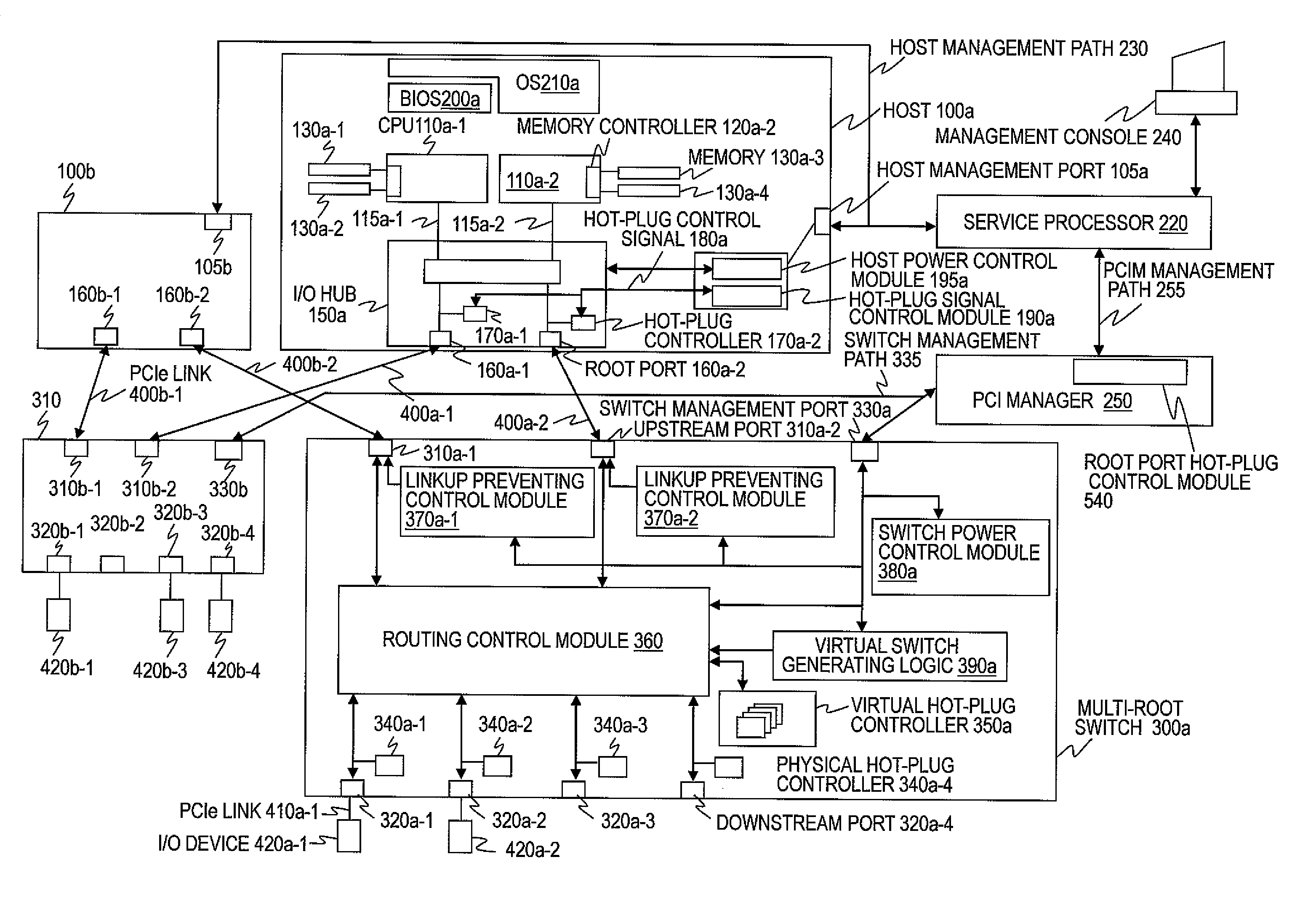
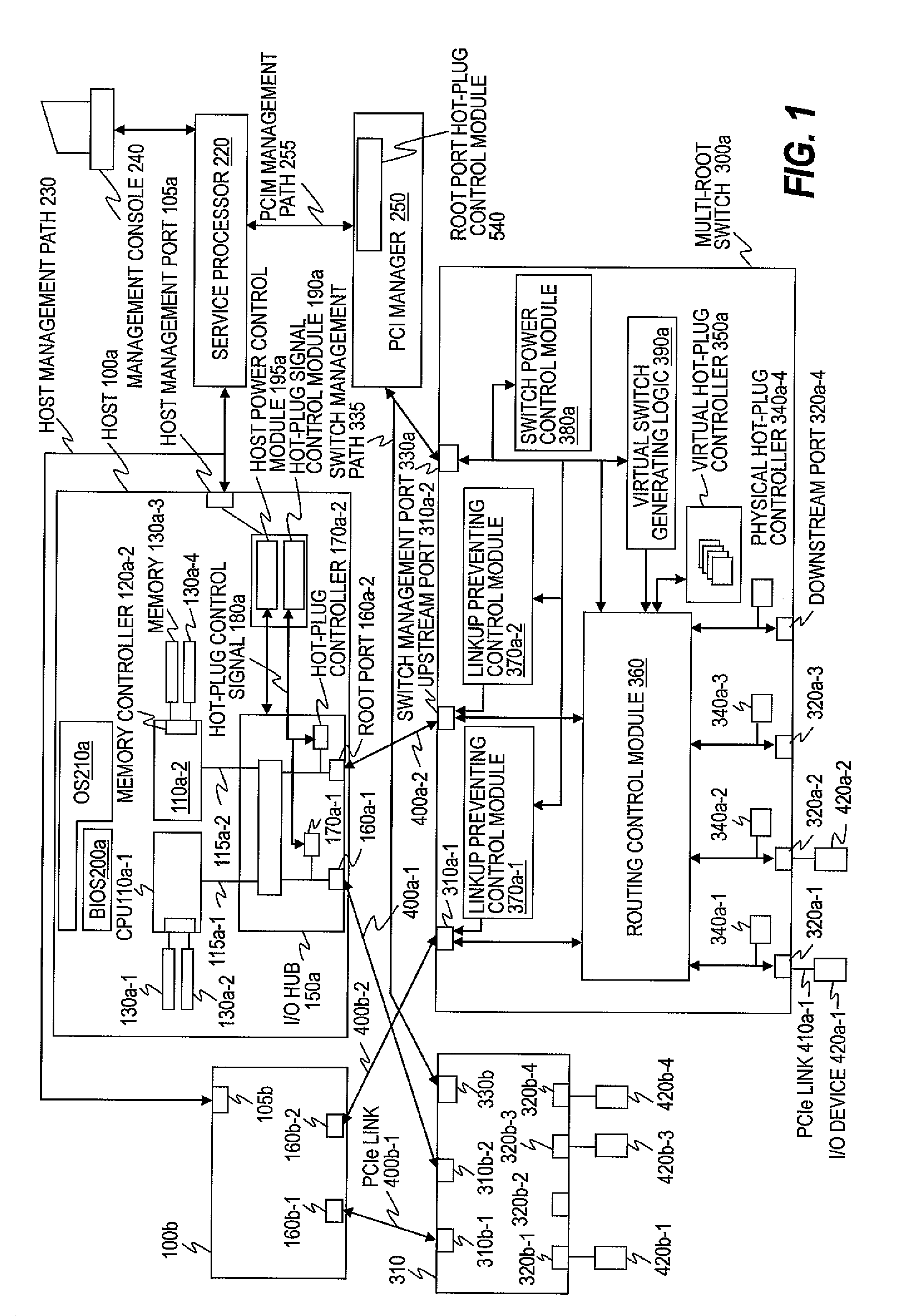
[0068]FIG. 1 is a block diagram illustrating the configuration of a computer system according to first and second embodiments of this invention.
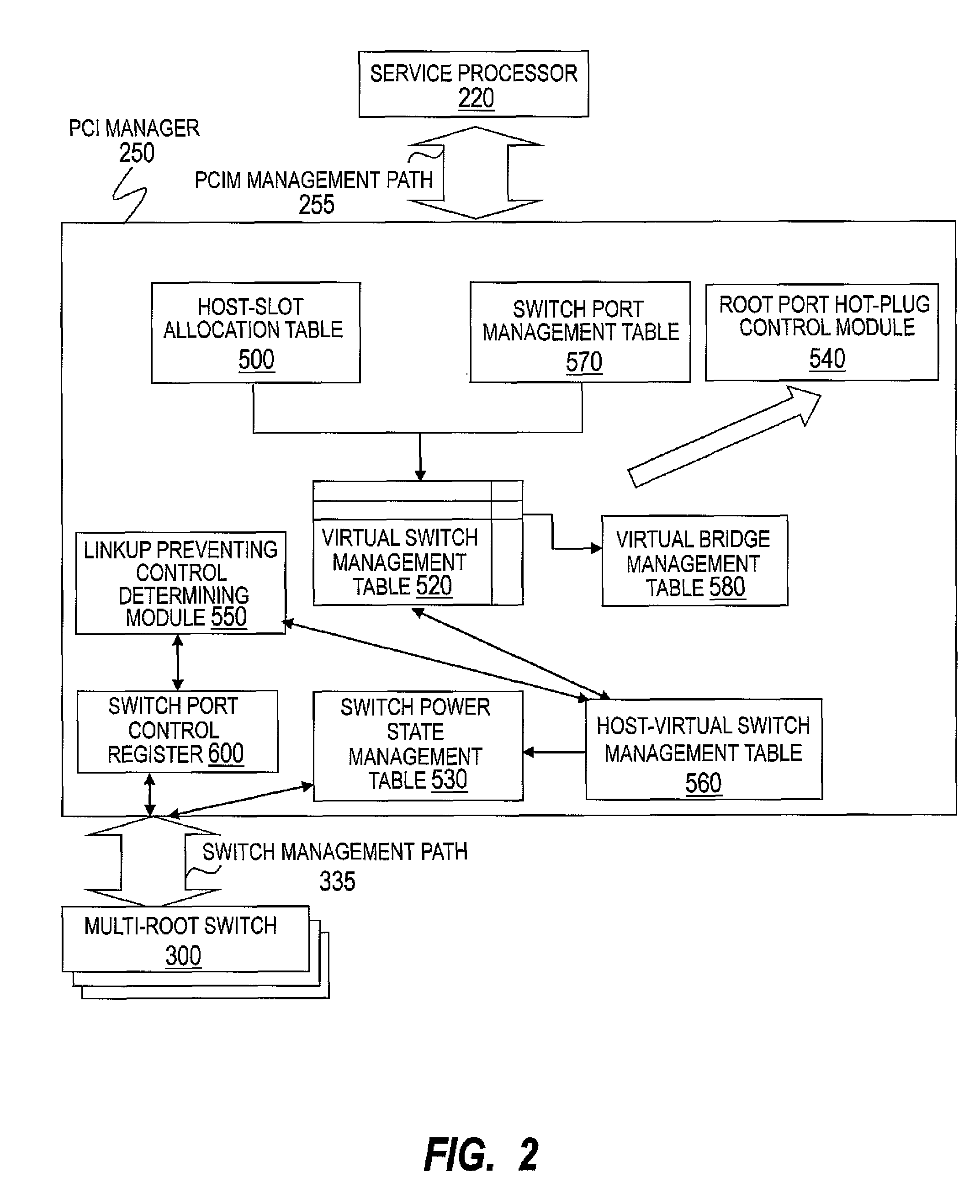
[0069]The computer system of the first embodiment includes hosts 100a and 100b, I / O devices 420a-1 and 420a-2 which are used by the host 100a, and I / O devices 420b-1, 420b-3 and 420b-4, which are used by the host 100b, multi-root switches 300a and 300b, the multi-root switch 300a connecting the hosts 100a and 100b to the I / O devices 420a-1 and 420a-2, the multi-root switch 300b connecting the hosts 100a and 100b to I / O devices 420b-1, 420b-3 and 420b-4, a PCI manager 250 (management server), which manages the multi-root switches 300a and 300b, and a service processor 220, which manages the hosts 100a and 100b. The service processor 220 has a function of relaying communication of the hosts 100a and 100b to and from the PCI manager 250. Alternatively, a network connecting the hosts 100a and 100b to and from the PCI manager...
second embodiment
[0287]A second embodiment of this invention is described next. The second embodiment relates to power control of the multi-root switches 300.
[0288]An initial state in the second embodiment is the same as the one in the first embodiment, namely, the one illustrated in FIGS. 3A and 3B and FIGS. 4A and 4B.
[0289]In the allocation of the slots 320 to the hosts 100 of FIGS. 3B and 4B, when the host A (100b) is powered off and the host B (100a) alone is powered on, the multi-root switch 300a does not need to be powered on because the host 100a uses none of the slots 320 that are placed under the multi-root switch 300a. A procedure of performing power saving control when the multi-root switch 300a does not need to be powered on is described later.
[0290]FIG. 27 is an explanatory diagram illustrating a switch power state management table 530a according to the second embodiment.
[0291]Any switch power state management table 530 uses a switch 531, which indicates the identifier of the multi-root...
third embodiment
[0337]300 Triggered by the Addition of Unallocated Slots 320 to a Running Host>
[0338]A third embodiment of this invention is described next. The third embodiment is an application of the second embodiment.
[0339]The computer system configuration and the host-slot allocation table 500 in an initial state of the third embodiment are the same as in the initial state of the second embodiment, namely, the same as in the initial state of the first embodiment. In the initial state of the third embodiment, the host 100b is powered off and the host 100a is running. The multi-root switch 300a is turned off and the multi-root switch 300b is turned on in the initial state of the third embodiment.
[0340]The host-virtual switch management table 560 and the switch power state management table 530 in the initial state of the third embodiment are the same as the host-virtual switch management table 560c and the switch power state management table 530c which are illustrated in FIG. 29 and FIG. 30, resp...
PUM
 Abstract
Description
Claims
Application Information
 - R&D
- Intellectual Property
- Life Sciences
- Materials
- Tech Scout
- Unparalleled Data Quality
- Higher Quality Content
- 60% Fewer Hallucinations
Browse by: Latest US Patents, China's latest patents, Technical Efficacy Thesaurus, Application Domain, Technology Topic, Popular Technical Reports.
© 2025 PatSnap. All rights reserved.Legal|Privacy policy|Modern Slavery Act Transparency Statement|Sitemap|About US| Contact US: help@patsnap.com


