
Knotless suture anchor

a technology of suture anchors and knots, which is applied in the field of knotless suture anchors, can solve the problems of not being able to achieve the same level of fixation into bone, and achieve the effect of reducing chafing

Active Publication Date: 2013-09-17
MEDOS INT SARL
View PDF26 Cites 9 Cited by
  • Summary
  • Abstract
  • Description
  • Claims
  • Application Information

AI Technical Summary

Benefits of technology

[0003]The present invention overcomes these and other limitations of the prior art in a simple and elegant design.
[0007]Preferably, a distal portion of the anchor member is smooth and free of the friction enhancement, thus easing its entry and alignment into the bone tunnel.
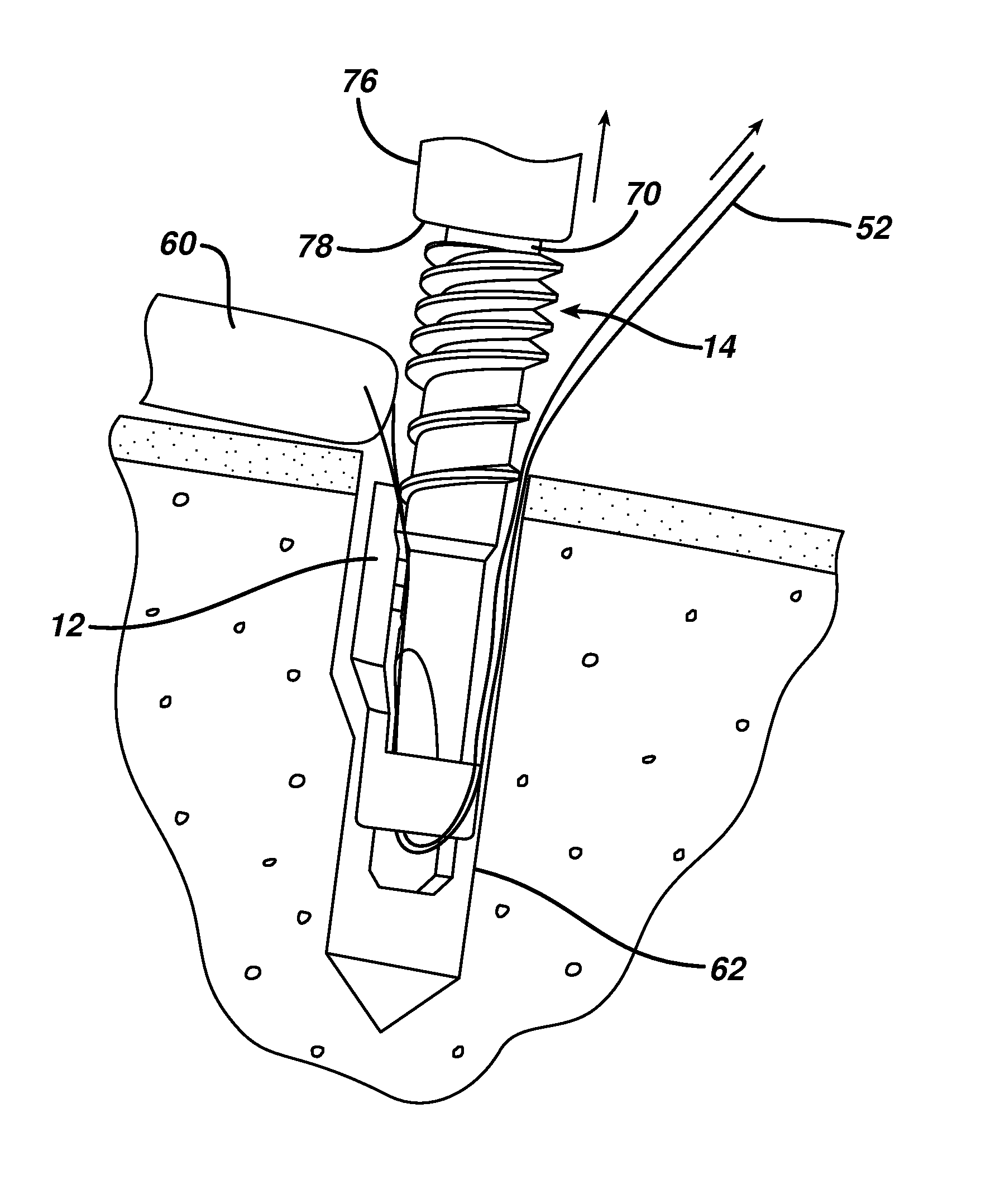
[0008]Preferably, one or more sutures are locked between the sidewall and the anchor member. An axially extending suture receiving recess can be provided along the sidewall adjacent the anchor member second lateral portion configured to keep the suture positioned therein despite rotation of the anchor member relative to the shell. Preferably, the suture extends proximally out of the shell over its proximal end so that the shell can act to protect the bone forming the bone tunnel from being abraded by the suture.
[0014]Preferably, the suture extends out of the bone hole by extending out of the shell over its proximal end toward the tissue whereby the shell thus reduces chafing between the suture and the bone.

Problems solved by technology

These anchors have many benefits but do not typically achieve the same level of fixation into bone as a regular threaded anchor.

Method used


Image

  • Knotless suture anchor
  • Knotless suture anchor
  • Knotless suture anchor

Examples


Embodiment Construction

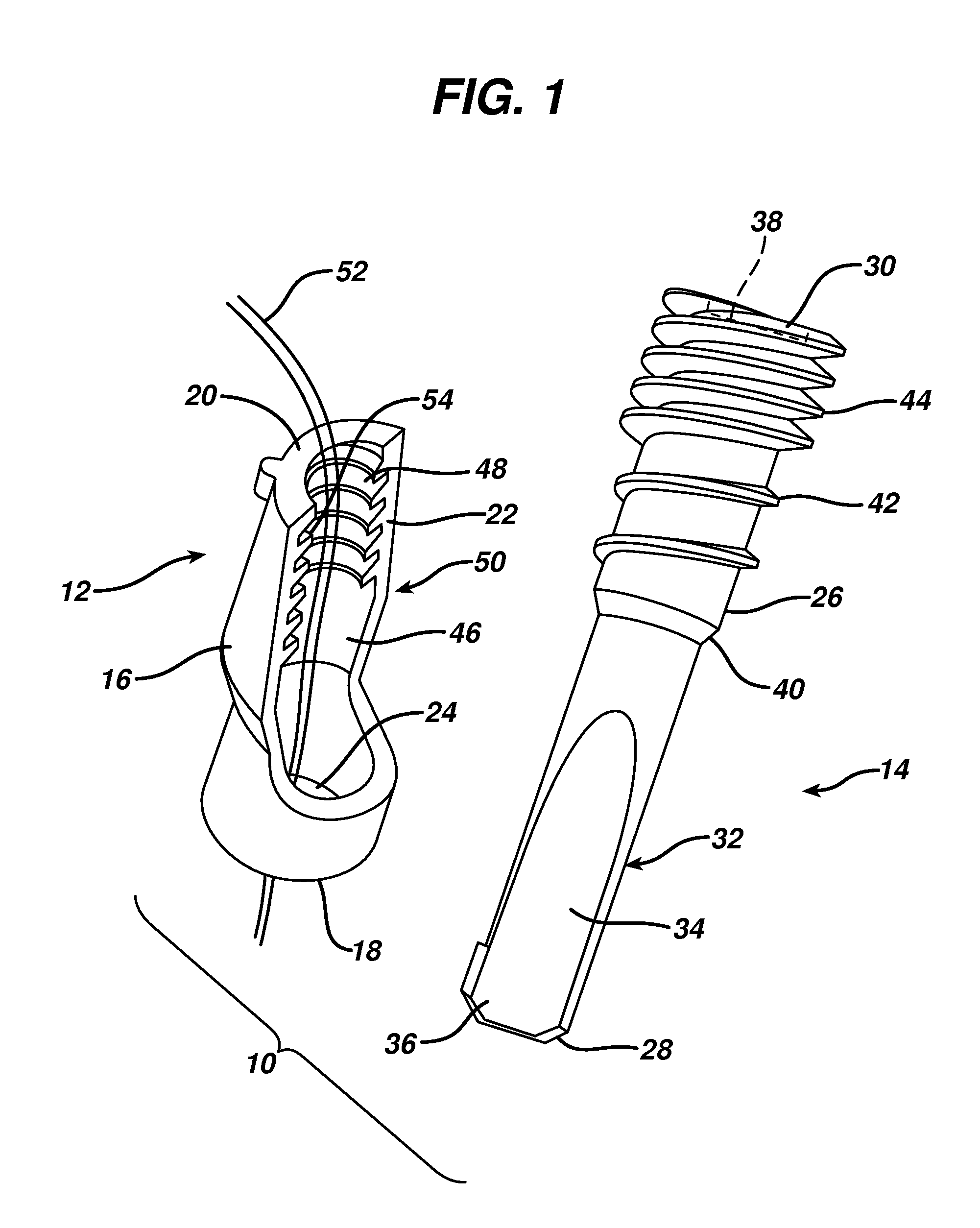
[0024]FIG. 1 illustrates a suture anchor 10 according to the present invention. It comprises a shell 12 and an anchor member 14 for receipt within the shell 12. The shell 12 comprises a body 16 having a distal end 18 and a proximal end 20 with sidewalls 22 therebetween defining an axial cannulation 24 adapted to receive the anchor member 14.

[0025]The anchor member 14 comprises an elongated body 26 having a distal end 28 and a proximal end 30 and which is sized to fit within the cannulation 24. A distal nose 32 of the body 26 has a reduced diameter and a smooth outer surface 34 lacking threading. A chamfer 36 at the distal end 28 eases entry into a bone tunnel (not shown in FIG. 1). A tool engaging recess 38, for example a hexagonal shape, is provided at the body proximal end 30. The body proximal end 30 has a slightly larger diameter creating a boss 40 at the smaller distal nose 32. Bone engaging threads 42 encircle the body 26 at its proximal end 30 and extend to the boss 40, with ...


PUM


Abstract

A suture anchor comprises a shell and an anchor member. The shell comprises a body having a distal end, a proximal end and sidewalls therebetween defining an axial cannulation therethrough. The anchor member comprises a body having a distal end and a proximal end which is sized to fit within the cannulation. The sidewalls define a lateral cut-out such that with the anchor member received within the cannulation a first lateral portion of the anchor member is exposed laterally and a second, laterally opposite, lateral portion of the anchor member is enclosed by the sidewalls. A friction enhancement on the first lateral portion frictionally engages a bone surface when the suture anchor is disposed within a bone tunnel defined by the bone surface. Suture is trapped between the shell and the anchor and also between the anchor and the bone surface.

Description

BACKGROUND[0001]This application relates to suture anchors and more particularly to knotless suture anchors.[0002]Knotless suture anchors allow fixation of suture to bone without requiring a surgeon to tie a knot to fix the suture with respect to the anchor. Certain knotless anchors capture suture in a notch at their distal end and are then inserted into a bone tunnel trapping the suture between the anchor and the bone to effect fixation. In soft bone the suture may cut into the bone over time, thereby loosening the tension in the suture. Certain other designs capture the suture between interlocking parts which also expand outwardly to limit their retraction from a bone tunnel. These anchors have many benefits but do not typically achieve the same level of fixation into bone as a regular threaded anchor.SUMMARY OF THE INVENTION[0003]The present invention overcomes these and other limitations of the prior art in a simple and elegant design.[0004]A suture anchor according to the prese...

Claims


Application Information

Patent Timeline
Patent Type & Authority Patents(United States)
IPC IPC(8): A61B17/04
CPCA61B17/0401A61B2017/0409A61B2017/0433A61B2017/0453A61B2017/044A61B2017/0448A61B2017/0451A61B2017/0438
Inventor LIZARDI, JOSE E.VENTO, MEGHAN
Owner MEDOS INT SARL
Learn More