Predicting transition from laminar to turbulent flow over a surface

a technology of turbulent flow and simulation, applied in the direction of air flow influencers, instruments, cad techniques, etc., can solve the problems of multiple complex simulations that may be prohibitively time-consuming, prohibitively time-consuming in early design phases, and interaction is not only time-consuming

Active Publication Date: 2013-09-17
AERION INTPROP MANAGEMENT CORP
View PDF40 Cites 4 Cited by
  • Summary
  • Abstract
  • Description
  • Claims
  • Application Information

AI Technical Summary

Problems solved by technology

Producing useful results often requires running complex simulations over a wide range of design variables and flight conditions.
Unless the transition prediction technique is efficient and easy to use, running multiple complex simulations may be prohibitively time-consuming in the earlier stages of aircraft design where major configuration changes are likely.
While LST-based analysis may produce accurate results, LST-based analysis may be prohibitively time-consuming in early design phases.
This interaction is not only time-consuming, but also requires that the user have experience interacting with the specific implementation of the LST-based analysis.
Thus, even with powerful computing resources, LST-based analysis may be impractical when iterating through a large number of design configurations in the early phases of aircraft design.
In contrast to those based on LST-based analysis, there are other transition prediction techniques that require very little user interaction but may sacrifice accuracy or reliability.
Without high accuracy and reliability, these techniques are less useful for iterating design configuration in the early phases of aircraft design.

Method used


Image

  • Predicting transition from laminar to turbulent flow over a surface
  • Predicting transition from laminar to turbulent flow over a surface
  • Predicting transition from laminar to turbulent flow over a surface

Examples


Embodiment Construction

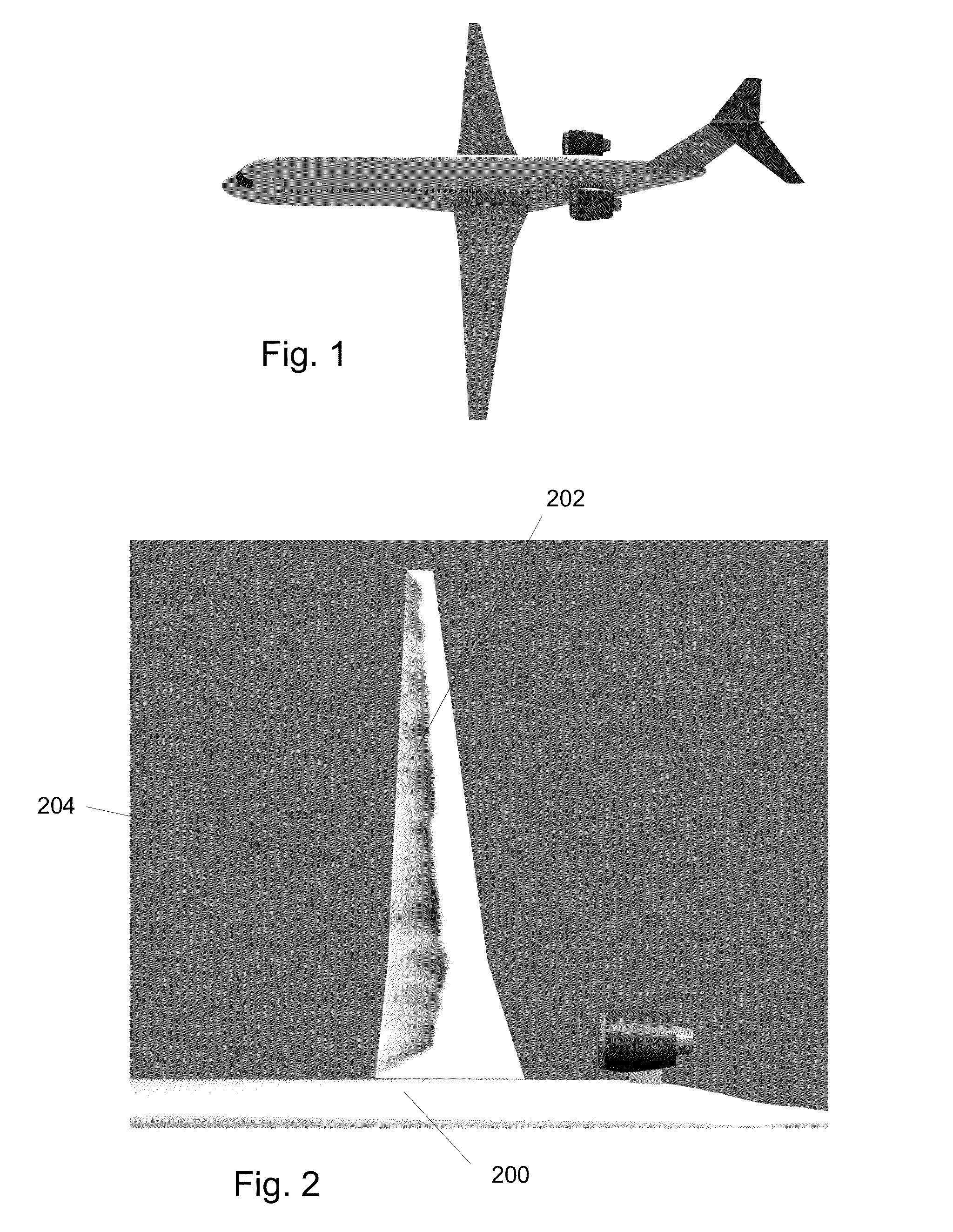
[0037]FIG. 1 illustrates a transonic natural-laminar-flow (NLF) concept jet. FIG. 2 shows a top view of a portion of a computer-generated simulation of the NLF jet. The shading on the wing 202 is proportional to the combined TS and crossflow instabilities on the upper surface at Mach 0.75 at 33,000 feet. The white areas on the wing 202 indicate regions where turbulent flow is predicted. As seen in FIG. 2, locations near fuselage 200 exhibit turbulent flow closer to the leading edge 204 of the wing 202 as compared to locations further away from fuselage 200.

[0038]The results depicted in FIG. 2 are an example of the output of a computer-generated simulation that allows a designer or engineer to evaluate the performance of an aircraft surface with respect to laminar flow. If necessary, changes can be made to the aircraft surface geometry to optimize or increase the amount of laminar flow. Additional simulations can be performed for modified aircraft surface geometry and the results can...


PUM


Abstract

A prediction of whether a point on a computer-generated surface is adjacent to laminar or turbulent flow is made using a transition prediction technique. A plurality of boundary-layer properties at the point are obtained from a steady-state solution of a fluid flow in a region adjacent to the point. A plurality of instability modes are obtained, each defined by one or more mode parameters. A vector of regressor weights is obtained for the known instability growth rates in a training dataset. For each instability mode in the plurality of instability modes, a covariance vector is determined, which is the covariance of a predicted local growth rate with the known instability growth rates. Each covariance vector is used with the vector of regressor weights to determine a predicted local growth rate at the point. Based on the predicted local growth rates, an n-factor envelope at the point is determined.

Description

STATEMENT REGARDING FEDERALLY SPONSORED RESEARCH OR DEVELOPMENT[0001]This invention was made with Government support under contract NNL08AA08C awarded by NASA. The Government has certain rights in the invention.BACKGROUND[0002]1. Field[0003]This application relates generally to simulating a fluid flow over a computer-generated surface and, more specifically, to predicting whether a point on the surface is adjacent to laminar or turbulent flow.[0004]2. Description of the Related Art[0005]Aerodynamic analysis of an aircraft moving through a fluid typically requires an accurate prediction of the properties of the fluid surrounding the aircraft. Accurate aerodynamic analysis is particularly important when designing aircraft surfaces, such as the surface of a wing or control surface. Typically, the outer surface of a portion of the aircraft, such as the surface of a wing, is modeled, either physically or by computer model, so that a simulation of the fluid flow can be performed and prope...

Claims


Application Information

Patent Timeline
Patent Type & Authority Patents(United States)
IPC IPC(8): G06F9/455
CPCG06F17/5018G06F17/5095G06F2217/16G06F30/23G06F30/15G06F2111/10Y02T90/00B64C21/10G06G7/57
Inventor RAJNARAYAN, DEVSTURDZA, PETER
Owner AERION INTPROP MANAGEMENT CORP
Why Eureka
Try Eureka